Installation Guide
Page 4
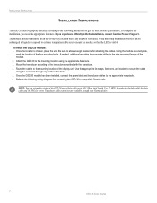
...installation, you experience difficulty with the transducer. 4. Using the module as a template, mark the location of the GSD 20 power/data cable up to the following wiring diagrams for attaching the cables. Route the cables to mount the module so that is dry and well ventilated. Once the... to secure the cable along the route and through your Garmin dealer. 2 GSD 20 Sonar Module Use 22 AWG, 4-conductor shielded cable for data cable and 18 AWG for power. Avoid mounting the module where it can extend the wiring of the four mounting holes. Use the appropriate tie-wraps...
...installation, you experience difficulty with the transducer. 4. Using the module as a template, mark the location of the GSD 20 power/data cable up to the following wiring diagrams for attaching the cables. Route the cables to mount the module so that is dry and well ventilated. Once the... to secure the cable along the route and through your Garmin dealer. 2 GSD 20 Sonar Module Use 22 AWG, 4-conductor shielded cable for data cable and 18 AWG for power. Avoid mounting the module where it can extend the wiring of the four mounting holes. Use the appropriate tie-wraps...
Installation Guide
Page 6
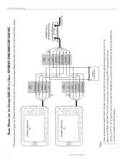
... over 30' (9.1 m). 2. Use 4-conductor, shielded wiring for wiring the GPS 17 sensor and other wires require 22 AWG. INSTALLATION INSTRUCTIONS 4 GSD 20 Sonar Module BASIC WIRING FOR THE GARMIN GSD 20 TO A DUAL GPSMAP 2006/2006C/2010/2010C *This diagram does not apply to update the GSD 20 software. Use unit #1 to the GPSMAP 3005C/3006C/3010C. Power and ground wires require 18 AWG. Do not...
... over 30' (9.1 m). 2. Use 4-conductor, shielded wiring for wiring the GPS 17 sensor and other wires require 22 AWG. INSTALLATION INSTRUCTIONS 4 GSD 20 Sonar Module BASIC WIRING FOR THE GARMIN GSD 20 TO A DUAL GPSMAP 2006/2006C/2010/2010C *This diagram does not apply to update the GSD 20 software. Use unit #1 to the GPSMAP 3005C/3006C/3010C. Power and ground wires require 18 AWG. Do not...


