Installation Guide
Page 1
GSD 20 Sounder Module installation instructions
GSD 20 Sounder Module installation instructions
Installation Guide
Page 2
... product should be reproduced, copied, transmitted, disseminated, downloaded, or stored in normal use and operation of such changes or improvements. Information in this document is being provided in the content without notice. If you . Within this manual may not be sent, freight charges prepaid, to notify any Garmin warranty service station. THE WARRANTIES AND REMEDIES CONTAINED HEREIN ARE EXCLUSIVE...
... product should be reproduced, copied, transmitted, disseminated, downloaded, or stored in normal use and operation of such changes or improvements. Information in this document is being provided in the content without notice. If you . Within this manual may not be sent, freight charges prepaid, to notify any Garmin warranty service station. THE WARRANTIES AND REMEDIES CONTAINED HEREIN ARE EXCLUSIVE...
Installation Guide
Page 3
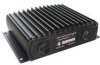
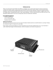
... results from multiple stations, including transmit frequency, range, and gain adjustments. Since mounting locations vary, see your local dealer or contact Garmin Product Support for choosing the Garmin GSD 20. Included Equipment: • GSD 20 Sounder Module • 30' (9.1 m) Power/Data Cable • Installation Guide for complete sounder control from your Garmin dealer immediately. Power/Data Connector LED Status Indicator Transducer Connector Mounting Holes GSD 20 Sonar Module 1 INTRODUCTION INTRODUCTION Thank you for further information. The larger the...
... results from multiple stations, including transmit frequency, range, and gain adjustments. Since mounting locations vary, see your local dealer or contact Garmin Product Support for choosing the Garmin GSD 20. Included Equipment: • GSD 20 Sounder Module • 30' (9.1 m) Power/Data Cable • Installation Guide for complete sounder control from your Garmin dealer immediately. Power/Data Connector LED Status Indicator Transducer Connector Mounting Holes GSD 20 Sonar Module 1 INTRODUCTION INTRODUCTION Thank you for further information. The larger the...
Installation Guide
Page 4
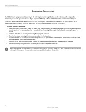
... GSD 20 power/data cable up to extreme temperatures. If needed, additional mounting holes may be submerged in liquids or exposed to 100' (30 m) total length. INSTALLATION INSTRUCTIONS INSTALLATION INSTRUCTIONS The GSD 20 must be mounted in an out-of the module. 2. The module should be properly installed according to the following wiring diagrams for connecting the GSD 20 to the instructions provided with the installation, contact Garmin Product Support. Mount the transducer according to compatible Garmin units...
... GSD 20 power/data cable up to extreme temperatures. If needed, additional mounting holes may be submerged in liquids or exposed to 100' (30 m) total length. INSTALLATION INSTRUCTIONS INSTALLATION INSTRUCTIONS The GSD 20 must be mounted in an out-of the module. 2. The module should be properly installed according to the following wiring diagrams for connecting the GSD 20 to the instructions provided with the installation, contact Garmin Product Support. Mount the transducer according to compatible Garmin units...
Installation Guide
Page 5
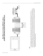
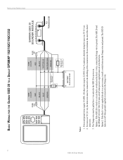
... GPS 17 sensor and other wires require 22 AWG. The GSD 20 information is transmitted to all units connected to one unit. INSTALLATION INSTRUCTIONS 3 Do not terminate the end of the extension run. GSD 20 Sonar Module BASIC WIRING FOR THE GARMIN GSD 20 TO A SINGLE GPSMAP 2006/2006C/2010/2010C/3005C/3006C/3010C FUSE 5 A WIRE COLOR RED BLACK ORANGE WHITE/BLUE WHITE/BROWN WIRE COLOR RED FUSE 2 A BLACK ORANGE WHITE/BLUE WHITE/BROWN GARMIN GSD 20 SOUNDER MODULE TO TRANSDUCER BATTERY...
... GPS 17 sensor and other wires require 22 AWG. The GSD 20 information is transmitted to all units connected to one unit. INSTALLATION INSTRUCTIONS 3 Do not terminate the end of the extension run. GSD 20 Sonar Module BASIC WIRING FOR THE GARMIN GSD 20 TO A SINGLE GPSMAP 2006/2006C/2010/2010C/3005C/3006C/3010C FUSE 5 A WIRE COLOR RED BLACK ORANGE WHITE/BLUE WHITE/BROWN WIRE COLOR RED FUSE 2 A BLACK ORANGE WHITE/BLUE WHITE/BROWN GARMIN GSD 20 SOUNDER MODULE TO TRANSDUCER BATTERY...
Installation Guide
Page 6
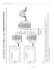
... wiring the GPS 17 sensor and other wires require 22 AWG. Refer to update the GSD 20 software. Use unit #1 to the GPSMAP 2006/2006C/2010/2010C Installation Instructions for runs over 30' (9.1 m), the drain wire must be connected to the shielding of the shield drain wire. 4. Do not terminate the end of the extension run. Refer to the GPSMAP 3005C/3006C/3010C. Power and ground wires...
... wiring the GPS 17 sensor and other wires require 22 AWG. Refer to update the GSD 20 software. Use unit #1 to the GPSMAP 2006/2006C/2010/2010C Installation Instructions for runs over 30' (9.1 m), the drain wire must be connected to the shielding of the shield drain wire. 4. Do not terminate the end of the extension run. Refer to the GPSMAP 3005C/3006C/3010C. Power and ground wires...
Installation Guide
Page 7
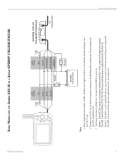
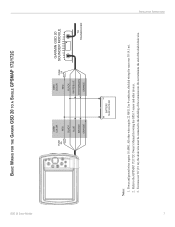
GSD 20 Sonar Module BASIC WIRING FOR THE GARMIN GSD 20 TO A SINGLE GPSMAP 276C/296/376C/396 INSTALLATION INSTRUCTIONS ON OFF FUSE 1.5A WIRE COLOR RED BLACK BLUE YELLOW SEE NOTE 3 ON OPTION 1 OFF WIRE COLOR RED FUSE 2A BLACK WHITE/BLUE WHITE/BROWN ORANGE BATTERY 10-35 VOLTS DC SEE NOTE 3 OPTION 2 GARMIN GSD 20 SOUNDER MODULE TO TRANSDUCER Notes: 1. The GSD 20 and the GPSMAP 276C/296/376C/396 turn on/off when ground...
GSD 20 Sonar Module BASIC WIRING FOR THE GARMIN GSD 20 TO A SINGLE GPSMAP 276C/296/376C/396 INSTALLATION INSTRUCTIONS ON OFF FUSE 1.5A WIRE COLOR RED BLACK BLUE YELLOW SEE NOTE 3 ON OPTION 1 OFF WIRE COLOR RED FUSE 2A BLACK WHITE/BLUE WHITE/BROWN ORANGE BATTERY 10-35 VOLTS DC SEE NOTE 3 OPTION 2 GARMIN GSD 20 SOUNDER MODULE TO TRANSDUCER Notes: 1. The GSD 20 and the GPSMAP 276C/296/376C/396 turn on/off when ground...
Installation Guide
Page 8
... WIRE COLOR RED FUSE 2A BLACK WHITE/BLUE WHITE/BROWN ORANGE BATTERY 10-35 VOLTS DC SEE NOTE 3 OPTION 2 GARMIN GSD 20 SOUNDER MODULE TO TRANSDUCER Notes: 1. The Orange wire must be pulled low (-) in order for runs over 30' (9.1 m), the drain wire must be connected to the Orange wire. Option 1: If the GSD 20 is wired to a circuit that is applied/removed to a power source, install a switch between...
... WIRE COLOR RED FUSE 2A BLACK WHITE/BLUE WHITE/BROWN ORANGE BATTERY 10-35 VOLTS DC SEE NOTE 3 OPTION 2 GARMIN GSD 20 SOUNDER MODULE TO TRANSDUCER Notes: 1. The Orange wire must be pulled low (-) in order for runs over 30' (9.1 m), the drain wire must be connected to the Orange wire. Option 1: If the GSD 20 is wired to a circuit that is applied/removed to a power source, install a switch between...
Installation Guide
Page 9
.... INSTALLATION INSTRUCTIONS 7 Power and ground wires require 18 AWG. Refer to the shielding of the shield drain wire. Use 4-conductor, shielded wiring for runs over 30' (9.1 m), the drain wire must be connected to the GPSMAP 172/172C Owner's Manual for wiring the GPS 17 sensor and other wires require 22 AWG. GSD 20 Sonar Module BASIC WIRING FOR THE GARMIN GSD 20 TO A SINGLE GPSMAP 172/172C FUSE 5A WIRE COLOR RED BLACK BLUE BROWN ORANGE WIRE COLOR RED FUSE...
.... INSTALLATION INSTRUCTIONS 7 Power and ground wires require 18 AWG. Refer to the shielding of the shield drain wire. Use 4-conductor, shielded wiring for runs over 30' (9.1 m), the drain wire must be connected to the GPSMAP 172/172C Owner's Manual for wiring the GPS 17 sensor and other wires require 22 AWG. GSD 20 Sonar Module BASIC WIRING FOR THE GARMIN GSD 20 TO A SINGLE GPSMAP 172/172C FUSE 5A WIRE COLOR RED BLACK BLUE BROWN ORANGE WIRE COLOR RED FUSE...
Installation Guide
Page 10
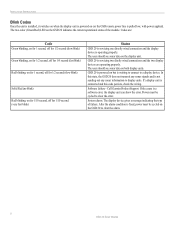
... blink) Status GSD 20 is servicing one directly wired connection and the display device is operating properly. Power must be cycled to display units. After the alarm condition is fixed, power must be cycled on the display unit. The user should see sonar data on the GSD 20 to a display device. The user should see sonar data on (or the GSD remote power line is pulled low, with power applied). Software failure - In this code persists, check the wiring. INSTALLATION INSTRUCTIONS Blink Codes Once the unit...
... blink) Status GSD 20 is servicing one directly wired connection and the display device is operating properly. Power must be cycled to display units. After the alarm condition is fixed, power must be cycled on the display unit. The user should see sonar data on the GSD 20 to a display device. The user should see sonar data on (or the GSD remote power line is pulled low, with power applied). Software failure - In this code persists, check the wiring. INSTALLATION INSTRUCTIONS Blink Codes Once the unit...
Installation Guide
Page 11
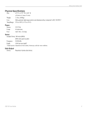
Data Output Source: Proprietary Garmin data format. INSTALLATION INSTRUCTIONS GSD 20 Sonar Module 9 AGC/3AG - 2.0 Amp Sonar Sounder Power: 500 watts (RMS) 4000 watts (peak to 70°C) Power Source: Usage: Fuse: 10-35 Vdc 18 watts max. Physical Specifications Size: 6.75" L x 4.75" W x 2.00" H (17.2cm x 12.1cm x 5.1cm) Weight: 1.5 lbs. (.680Kg) Case: Fully gasketed, high-impact plastic and aluminum alloy, waterproof to...
Data Output Source: Proprietary Garmin data format. INSTALLATION INSTRUCTIONS GSD 20 Sonar Module 9 AGC/3AG - 2.0 Amp Sonar Sounder Power: 500 watts (RMS) 4000 watts (peak to 70°C) Power Source: Usage: Fuse: 10-35 Vdc 18 watts max. Physical Specifications Size: 6.75" L x 4.75" W x 2.00" H (17.2cm x 12.1cm x 5.1cm) Weight: 1.5 lbs. (.680Kg) Case: Fully gasketed, high-impact plastic and aluminum alloy, waterproof to...

Installation Guide
Page 12
or its subsidiaries Garmin International, Inc. 1200 East 151st Street, Olathe, Kansas 66062, U.S.A. © Copyright 2004, 2005 Garmin Ltd. Garmin Corporation No. 68, Jangshu 2nd Road, Shijr, Taipei County, Taiwan www.garmin.com Part Number 190-00255-00 Rev. Unit 5, The Quadrangle, Abbey Park Industrial Estate, Romsey, SO51 9DL, U.K. E Garmin (Europe) Ltd.
or its subsidiaries Garmin International, Inc. 1200 East 151st Street, Olathe, Kansas 66062, U.S.A. © Copyright 2004, 2005 Garmin Ltd. Garmin Corporation No. 68, Jangshu 2nd Road, Shijr, Taipei County, Taiwan www.garmin.com Part Number 190-00255-00 Rev. Unit 5, The Quadrangle, Abbey Park Industrial Estate, Romsey, SO51 9DL, U.K. E Garmin (Europe) Ltd.


