Installation Guide
Page 3
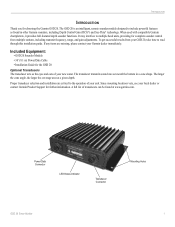
.../Data Cable • Installation Guide for choosing the Garmin GSD 20. Power/Data Connector LED Status Indicator Transducer Connector Mounting Holes GSD 20 Sonar Module 1 The larger the cone angle, the larger the coverage area at www.garmin.com. The GSD 20 is an intelligent, remote sounder module designed to the operation of your GSD 20, take time to multiple head units, providing for...
.../Data Cable • Installation Guide for choosing the Garmin GSD 20. Power/Data Connector LED Status Indicator Transducer Connector Mounting Holes GSD 20 Sonar Module 1 The larger the cone angle, the larger the coverage area at www.garmin.com. The GSD 20 is an intelligent, remote sounder module designed to the operation of your GSD 20, take time to multiple head units, providing for...
Installation Guide
Page 4
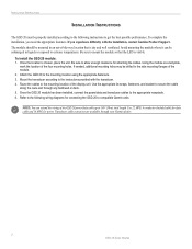
... cable up to secure the cable along the route and through your Garmin dealer. 2 GSD 20 Sonar Module Attach the GSD 20 to the instructions provided with the installation, contact Garmin Product Support. Mount the transducer according to the mounting location using the appropriate fasteners. 3. Once the GSD 20 module has been installed, connect the power/data and transducer cables to...
... cable up to secure the cable along the route and through your Garmin dealer. 2 GSD 20 Sonar Module Attach the GSD 20 to the instructions provided with the installation, contact Garmin Product Support. Mount the transducer according to the mounting location using the appropriate fasteners. 3. Once the GSD 20 module has been installed, connect the power/data and transducer cables to...
Installation Guide
Page 5
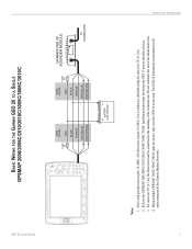
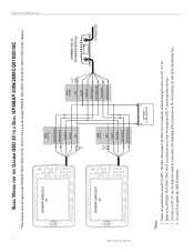
.../2006C/2010/2010C/3005C/3006C/3010C Installation Instructions for wiring the GPS 17 sensor and other wires require 22 AWG. When multiple GPSMAP 3005C/3006C/3010C units are in use, only wire the GSD 20 to the Garmin Marnine Network. GSD 20 Sonar Module BASIC WIRING FOR THE GARMIN GSD 20 TO A SINGLE GPSMAP 2006/2006C/2010/2010C/3005C/3006C/3010C FUSE...
.../2006C/2010/2010C/3005C/3006C/3010C Installation Instructions for wiring the GPS 17 sensor and other wires require 22 AWG. When multiple GPSMAP 3005C/3006C/3010C units are in use, only wire the GSD 20 to the Garmin Marnine Network. GSD 20 Sonar Module BASIC WIRING FOR THE GARMIN GSD 20 TO A SINGLE GPSMAP 2006/2006C/2010/2010C/3005C/3006C/3010C FUSE...
Installation Guide
Page 6
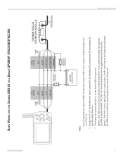
Use 4-conductor, shielded wiring for wiring the GPS 17 sensor and other wires require 22 AWG. Do not terminate the end of the extension run. Use unit #1 to the GPSMAP 3005C/3006C/3010C. INSTALLATION INSTRUCTIONS 4 GSD 20 Sonar Module BASIC WIRING FOR THE GARMIN GSD 20 TO A DUAL GPSMAP 2006/2006C/2010/2010C *This diagram does not apply to update...
Use 4-conductor, shielded wiring for wiring the GPS 17 sensor and other wires require 22 AWG. Do not terminate the end of the extension run. Use unit #1 to the GPSMAP 3005C/3006C/3010C. INSTALLATION INSTRUCTIONS 4 GSD 20 Sonar Module BASIC WIRING FOR THE GARMIN GSD 20 TO A DUAL GPSMAP 2006/2006C/2010/2010C *This diagram does not apply to update...
Installation Guide
Page 7
... and ground wires require 18 AWG. For runs over 30' (9.1 m), the drain wire must be connected to the Red wire. GSD 20 Sonar Module BASIC WIRING FOR THE GARMIN GSD 20 TO A SINGLE GPSMAP 276C/296/376C/396 INSTALLATION INSTRUCTIONS ON OFF FUSE 1.5A WIRE COLOR RED BLACK BLUE YELLOW SEE NOTE 3 ON... RED FUSE 2A BLACK WHITE/BLUE WHITE/BROWN ORANGE BATTERY 10-35 VOLTS DC SEE NOTE 3 OPTION 2 GARMIN GSD 20 SOUNDER MODULE TO TRANSDUCER Notes: 1. All other wires require 22 AWG. The GSD 20 turns on/off when power is switched on the Red (+) wire, connect the Orange wire to power on...
... and ground wires require 18 AWG. For runs over 30' (9.1 m), the drain wire must be connected to the Red wire. GSD 20 Sonar Module BASIC WIRING FOR THE GARMIN GSD 20 TO A SINGLE GPSMAP 276C/296/376C/396 INSTALLATION INSTRUCTIONS ON OFF FUSE 1.5A WIRE COLOR RED BLACK BLUE YELLOW SEE NOTE 3 ON... RED FUSE 2A BLACK WHITE/BLUE WHITE/BROWN ORANGE BATTERY 10-35 VOLTS DC SEE NOTE 3 OPTION 2 GARMIN GSD 20 SOUNDER MODULE TO TRANSDUCER Notes: 1. All other wires require 22 AWG. The GSD 20 turns on/off when power is switched on the Red (+) wire, connect the Orange wire to power on...
Installation Guide
Page 8
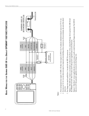
... the GPSMAP 182/182C/192C/232 turns on . The Orange wire must be pulled low (-) in order for the GSD 20 to the shielding of the shield drain wire. 3. The GSD 20 turns on the Red (+) wire, connect the Orange wire to a power source, install a switch between the Orange wire and ...or off when power is applied directly to ground. Do not terminate the end of the extension run. INSTALLATION INSTRUCTIONS ON OFF 6 GSD 20 Sonar Module BASIC WIRING FOR THE GARMIN GSD 20 TO A SINGLE GPSMAP 182/182C/192C/232 FUSE 1.5A WIRE COLOR RED BLACK BLUE BROWN SEE NOTE 3 ON OPTION 1 OFF WIRE...
... the GPSMAP 182/182C/192C/232 turns on . The Orange wire must be pulled low (-) in order for the GSD 20 to the shielding of the shield drain wire. 3. The GSD 20 turns on the Red (+) wire, connect the Orange wire to a power source, install a switch between the Orange wire and ...or off when power is applied directly to ground. Do not terminate the end of the extension run. INSTALLATION INSTRUCTIONS ON OFF 6 GSD 20 Sonar Module BASIC WIRING FOR THE GARMIN GSD 20 TO A SINGLE GPSMAP 182/182C/192C/232 FUSE 1.5A WIRE COLOR RED BLACK BLUE BROWN SEE NOTE 3 ON OPTION 1 OFF WIRE...
Installation Guide
Page 9
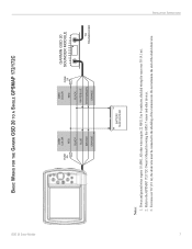
... runs over 30' (9.1 m), the drain wire must be connected to the GPSMAP 172/172C Owner's Manual for wiring the GPS 17 sensor and other wires require 22 AWG. GSD 20 Sonar Module BASIC WIRING FOR THE GARMIN GSD 20 TO A SINGLE GPSMAP 172/172C FUSE 5A WIRE COLOR RED BLACK BLUE BROWN ORANGE WIRE COLOR RED FUSE 2A BLACK...
... runs over 30' (9.1 m), the drain wire must be connected to the GPSMAP 172/172C Owner's Manual for wiring the GPS 17 sensor and other wires require 22 AWG. GSD 20 Sonar Module BASIC WIRING FOR THE GARMIN GSD 20 TO A SINGLE GPSMAP 172/172C FUSE 5A WIRE COLOR RED BLACK BLUE BROWN ORANGE WIRE COLOR RED FUSE 2A BLACK...
Installation Guide
Page 10
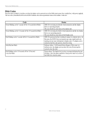
...switches on when the display unit is powered on (or the GSD remote power line is fixed, power must be cycled on the GSD 20 to clear the alarm. 8 GSD 20 Sonar Module GSD 20 is waiting to connect to a display device. GSD 20 is powered on but is servicing two dirctly wired connections and...on for 1/10 second, off for 1/10 second (very fast blink) Status GSD 20 is servicing one directly wired connection and the display device is not sending out any sonar signals and is operating properly. Call Garmin Product Support. If a display unit is a software error, the display unit ...
...switches on when the display unit is powered on (or the GSD remote power line is fixed, power must be cycled on the GSD 20 to clear the alarm. 8 GSD 20 Sonar Module GSD 20 is waiting to connect to a display device. GSD 20 is powered on but is servicing two dirctly wired connections and...on for 1/10 second, off for 1/10 second (very fast blink) Status GSD 20 is servicing one directly wired connection and the display device is not sending out any sonar signals and is operating properly. Call Garmin Product Support. If a display unit is a software error, the display unit ...
Installation Guide
Page 11
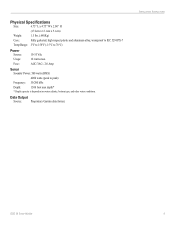
... Power: 500 watts (RMS) 4000 watts (peak to 70°C) Power Source: Usage: Fuse: 10-35 Vdc 18 watts max. INSTALLATION INSTRUCTIONS GSD 20 Sonar Module 9 Data Output Source: Proprietary Garmin data format. Physical Specifications Size: 6.75" L x 4.75" W x 2.00" H (17.2cm x 12.1cm x 5.1cm) Weight: 1.5 lbs. (.680Kg) Case: Fully gasketed, high-impact plastic...
... Power: 500 watts (RMS) 4000 watts (peak to 70°C) Power Source: Usage: Fuse: 10-35 Vdc 18 watts max. INSTALLATION INSTRUCTIONS GSD 20 Sonar Module 9 Data Output Source: Proprietary Garmin data format. Physical Specifications Size: 6.75" L x 4.75" W x 2.00" H (17.2cm x 12.1cm x 5.1cm) Weight: 1.5 lbs. (.680Kg) Case: Fully gasketed, high-impact plastic...

