
2006/2010/GPS 17 Installation
Page 10
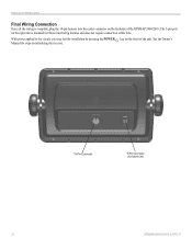
See the Owner's Manual for steps on initializing the receiver. 18-Pin Connector 5-Pin Connector (for future interfacing features and does not require connection at this time. INSTALLATION INSTRUCTIONS Final Wiring Connection Once all the wiring is intended for future use) 10 GPSMAP 2006C/2010C & GPS 17 The 5-pin port on the right side is complete, plug the 18-pin harness into the center connector on the front of the GPSMAP 2006/2010. With power applied to the circuit, you may test the installation by pressing the POWER key on the backside of the unit.
See the Owner's Manual for steps on initializing the receiver. 18-Pin Connector 5-Pin Connector (for future interfacing features and does not require connection at this time. INSTALLATION INSTRUCTIONS Final Wiring Connection Once all the wiring is intended for future use) 10 GPSMAP 2006C/2010C & GPS 17 The 5-pin port on the right side is complete, plug the 18-pin harness into the center connector on the front of the GPSMAP 2006/2010. With power applied to the circuit, you may test the installation by pressing the POWER key on the backside of the unit.

Declaration of Conformity
Page 1
Estate, Romsey, Hampshire, SO51 9DL, U.K. Information Technology Equipment (Global Positioning System Receiver) GPS 16HVS GPS 16LVC GPS 16LVS The undersigned does hereby declare that the equipment complies to which Conformity is Declared: 89/... Manufactured by: Manufacture's Address: Authorised Representative: Type of Equipment: Model Number(s): GARMIN International & GARMIN Corporation 1200 E. 151st Street No.68, Jangshu 2nd Rd., Olathe, Kansas 66062 Shijr, Taipei County, U.S.A TAIWAN, R.O.C. GARMIN (Europe) Ltd, The Quadrangle, Abbey Park Ind. Issued: 08/04/2005 Revised...
Estate, Romsey, Hampshire, SO51 9DL, U.K. Information Technology Equipment (Global Positioning System Receiver) GPS 16HVS GPS 16LVC GPS 16LVS The undersigned does hereby declare that the equipment complies to which Conformity is Declared: 89/... Manufactured by: Manufacture's Address: Authorised Representative: Type of Equipment: Model Number(s): GARMIN International & GARMIN Corporation 1200 E. 151st Street No.68, Jangshu 2nd Rd., Olathe, Kansas 66062 Shijr, Taipei County, U.S.A TAIWAN, R.O.C. GARMIN (Europe) Ltd, The Quadrangle, Abbey Park Ind. Issued: 08/04/2005 Revised...

Declaration of Conformity
Page 2
GARMIN (Europe) Ltd, The Quadrangle, Abbey Park Ind. Estate, Romsey, Hampshire, SO51 9DL, U.K. Information Technology Equipment (Global Positioning System Receiver) GPS 17HVS The undersigned does hereby declare that the equipment complies to which Conformity is Declared: 89/336/EEC, ...Technology Equipment Manufactured by: Manufacture's Address: Authorised Representative: Type of Council Directive: Standard to the above Directives Paul Morrow Quality Manager GARMIN (Europe) Ltd Date: 8th April 2005 Issued: 08/04/2005 Revised: 08/04/2005 Page: 1 of 1 DECLARATION of CONFORMITY Application...
GARMIN (Europe) Ltd, The Quadrangle, Abbey Park Ind. Estate, Romsey, Hampshire, SO51 9DL, U.K. Information Technology Equipment (Global Positioning System Receiver) GPS 17HVS The undersigned does hereby declare that the equipment complies to which Conformity is Declared: 89/336/EEC, ...Technology Equipment Manufactured by: Manufacture's Address: Authorised Representative: Type of Council Directive: Standard to the above Directives Paul Morrow Quality Manager GARMIN (Europe) Ltd Date: 8th April 2005 Issued: 08/04/2005 Revised: 08/04/2005 Page: 1 of 1 DECLARATION of CONFORMITY Application...

Installation Guide
Page 2
...Tel. 44/0870.8501241 Tel. 886/2.2642.9199 Fax 44/0870.8501251 Fax 886/2.2642.9099 All rights reserved. Visit the Garmin Web site (www.garmin.com) for any revision hereto is strictly prohibited. Note: Operation of this device is subject to print one copy of this ... of this and other electronic storage medium to be used without notice. A Printed in the content without obligation to notify any interference received, including interference that any unauthorized commercial distribution of this document is subject to download a single copy of this device must contain the ...
...Tel. 44/0870.8501241 Tel. 886/2.2642.9199 Fax 44/0870.8501251 Fax 886/2.2642.9099 All rights reserved. Visit the Garmin Web site (www.garmin.com) for any revision hereto is strictly prohibited. Note: Operation of this device is subject to print one copy of this ... of this and other electronic storage medium to be used without notice. A Printed in the content without obligation to notify any interference received, including interference that any unauthorized commercial distribution of this document is subject to download a single copy of this device must contain the ...

Installation Guide
Page 3
... alert you have any difficulty while using your original sales receipt in death or serious injury. Keep your GPS 17, or if you to avoid unsafe practices. at sales@garmin.com. i or by phone: 913/397.8200 or 800/800.1020, Monday-Friday, 8 AM-5 PM Central Time;... 703/684.4481 Fax. 703/836.4229 www.rtcm.org GPS 17 Installation Guide INTRODUCTION Introduction i Specifications 1 Mounting the Receiver 2 Mounting Location Tips 3 Routing the Cable 5 Wiring the GPS 17 6 Wire Color Code 6 Wiring Diagrams 7 Using the GPS 17 10 First Time Fix 10 Limited Warranty 11 This manual...
... alert you have any difficulty while using your original sales receipt in death or serious injury. Keep your GPS 17, or if you to avoid unsafe practices. at sales@garmin.com. i or by phone: 913/397.8200 or 800/800.1020, Monday-Friday, 8 AM-5 PM Central Time;... 703/684.4481 Fax. 703/836.4229 www.rtcm.org GPS 17 Installation Guide INTRODUCTION Introduction i Specifications 1 Mounting the Receiver 2 Mounting Location Tips 3 Routing the Cable 5 Wiring the GPS 17 6 Wire Color Code 6 Wiring Diagrams 7 Using the GPS 17 10 First Time Fix 10 Limited Warranty 11 This manual...

Installation Guide
Page 4
...purpose requiring precise measurement of authorized government charts. GPS 17 Installation Guide INTRODUCTION Warning Failure to avoid the following potentially hazardous situations may result in injury or property damage. When navigating, carefully compare information received from street signs, visual sightings, and maps.....garmin.com/prop65. For safety, always resolve any navigation device can be used to replace, the use the GPS 17 for its components contain chemicals known to the State of all GPS equipment, including the GPS 17. ii The Global Positioning System (GPS)...
...purpose requiring precise measurement of authorized government charts. GPS 17 Installation Guide INTRODUCTION Warning Failure to avoid the following potentially hazardous situations may result in injury or property damage. When navigating, carefully compare information received from street signs, visual sightings, and maps.....garmin.com/prop65. For safety, always resolve any navigation device can be used to replace, the use the GPS 17 for its components contain chemicals known to the State of all GPS equipment, including the GPS 17. ii The Global Positioning System (GPS)...

Installation Guide
Page 5
... 60529 IPX7 level (immersion in 1 meter of water for 30 minutes). SPECIFICATIONS SPECIFICATIONS Physical Characteristics Size: 3.58" (91.0 mm) diameter, 3.60" (91.5 mm) high Weight: GPS 17 only: 7.1 oz (201 g) With 30 foot cable: 16.8 oz (465 g) With pole mount adapter & cable: 18.2 oz (516 grams) Pole mount adapter alone: 1.4 oz...
... 60529 IPX7 level (immersion in 1 meter of water for 30 minutes). SPECIFICATIONS SPECIFICATIONS Physical Characteristics Size: 3.58" (91.0 mm) diameter, 3.60" (91.5 mm) high Weight: GPS 17 only: 7.1 oz (201 g) With 30 foot cable: 16.8 oz (465 g) With pole mount adapter & cable: 18.2 oz (516 grams) Pole mount adapter alone: 1.4 oz...
Installation Guide
Page 6
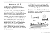
The receiver base fits a standard 1-inch, 14 threads-per-inch marine mount. Check with your Garmin dealer or a marine retailer for a suitable mount for GPS units are other electronic equipment, fan motors, engine ignition, alternators, generators, radars, and VHF radio transmissions. If you find a suitable location, permanently install the GPS 17. OK Radar...
The receiver base fits a standard 1-inch, 14 threads-per-inch marine mount. Check with your Garmin dealer or a marine retailer for a suitable mount for GPS units are other electronic equipment, fan motors, engine ignition, alternators, generators, radars, and VHF radio transmissions. If you find a suitable location, permanently install the GPS 17. OK Radar...
Installation Guide
Page 7
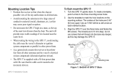
Mounting Location Tips • Position the receiver so that it is supplied with a 30-foot power/data cable. Turn the GPS 17 upside down. Use an 11/64" drill bit to drill a hole at least three feet from all directions. • Avoid mounting the antenna next ...the M4 screws. Be sure that will provide more than the boat. Use the template to other power lines. • As a general rule, mount the receiver at each marked location. 3. To create a template, punch a hole in all other antennas and the vessel's electrical system components (alternator/ignition system). • The...
Mounting Location Tips • Position the receiver so that it is supplied with a 30-foot power/data cable. Turn the GPS 17 upside down. Use an 11/64" drill bit to drill a hole at least three feet from all directions. • Avoid mounting the antenna next ...the M4 screws. Be sure that will provide more than the boat. Use the template to other power lines. • As a general rule, mount the receiver at each marked location. 3. To create a template, punch a hole in all other antennas and the vessel's electrical system components (alternator/ignition system). • The...

Installation Guide
Page 10
...is used for these items. 54 3 21 98 76 DB-9 Female Serial Connector 13 7 3 21 25 14 DB-25 Female Serial Connector Garmin recommends that the GPS 17 and the receiving device share the same ground. You need a DB-9 or DB-25 serial connector (normally female) if you install a 1A fuse on ...the power (+) line of the receiving device. Wire Color Code Red: Power (+) 8-40 VDC. WIRING THE GPS 17 WIRING THE GPS 17 After mounting the GPS 17 in the desired location, connect the wiring. Connect the GPS 17's Port 1 Data In, Data Out, Remote On/Off, and Ground...
...is used for these items. 54 3 21 98 76 DB-9 Female Serial Connector 13 7 3 21 25 14 DB-25 Female Serial Connector Garmin recommends that the GPS 17 and the receiving device share the same ground. You need a DB-9 or DB-25 serial connector (normally female) if you install a 1A fuse on ...the power (+) line of the receiving device. Wire Color Code Red: Power (+) 8-40 VDC. WIRING THE GPS 17 WIRING THE GPS 17 After mounting the GPS 17 in the desired location, connect the wiring. Connect the GPS 17's Port 1 Data In, Data Out, Remote On/Off, and Ground...
Installation Guide
Page 13
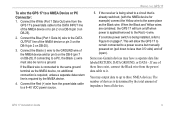
...a ground. If connecting to a PC, the Black (-) wire must also be run to a NMEA Device or PC Connector: 1. If the receiver is determined by the NMEA device. 4. GPS 17 Installation Guide 9 This will turn on page 7. Connect the Blue (Port 1 Data In) wire to the same ground terminal as the ... the DATA OUTPUT line of impedance from all devices. You may have a separate data line labeled RETURN, DATA GROUND, or DATA -. Some non-Garmin devices may output data to up to less than 0.5 volts) and off when power is required by the total amount of the NMEA device or...
...a ground. If connecting to a PC, the Black (-) wire must also be run to a NMEA Device or PC Connector: 1. If the receiver is determined by the NMEA device. 4. GPS 17 Installation Guide 9 This will turn on page 7. Connect the Blue (Port 1 Data In) wire to the same ground terminal as the ... the DATA OUTPUT line of impedance from all devices. You may have a separate data line labeled RETURN, DATA GROUND, or DATA -. Some non-Garmin devices may output data to up to less than 0.5 volts) and off when power is required by the total amount of the NMEA device or...
Installation Guide
Page 14
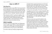
...States that adheres to improve the overall integrity of the GPS signal and increase position accuracy for users in AutoLocate® mode, which allows the receiver to 20 minutes. When turned on the Garmin Web site. USING THE GPS 17 USING THE GPS 17 First Time Fix The first time you turn... on your GPS unit with increased accuracy at any location in September 2002 of ...
...States that adheres to improve the overall integrity of the GPS signal and increase position accuracy for users in AutoLocate® mode, which allows the receiver to 20 minutes. When turned on the Garmin Web site. USING THE GPS 17 USING THE GPS 17 First Time Fix The first time you turn... on your GPS unit with increased accuracy at any location in September 2002 of ...
Technical Specifications
Page 3
... ...2 1.4 Overview ...3 1.5 Features ...3 1.6 GPS 16/17 Series...4 1.6.1 GPS 16LVS & 16HVS ...4 1.6.2 GPS 17HVS ...4 1.7 Technical Specifications...5 1.7.1 Physical Characteristics ...5 1.7.1.1 Size ...5 1.7.1.2 Weight ...5 1.7.1.3 Cable...5 1.7.1.4 Color...5 1.7.1.5 Case Material...5 1.7.1.6 GPS 17HVS Thread Specifications 5 1.7.2 Electrical Characteristics ...5 1.7.2.1 Input Voltage ...5 1.7.2.2 Input Current ...5 1.7.2.3 Standby Current...5 1.7.2.4 GPS Receiver Sensitivity 5 1.7.3 Environmental Characteristics 5 1.7.4 GPS Performance...6 1.7.4.1 Receiver...6 1.7.4.2 Acquisition Times...
... ...2 1.4 Overview ...3 1.5 Features ...3 1.6 GPS 16/17 Series...4 1.6.1 GPS 16LVS & 16HVS ...4 1.6.2 GPS 17HVS ...4 1.7 Technical Specifications...5 1.7.1 Physical Characteristics ...5 1.7.1.1 Size ...5 1.7.1.2 Weight ...5 1.7.1.3 Cable...5 1.7.1.4 Color...5 1.7.1.5 Case Material...5 1.7.1.6 GPS 17HVS Thread Specifications 5 1.7.2 Electrical Characteristics ...5 1.7.2.1 Input Voltage ...5 1.7.2.2 Input Current ...5 1.7.2.3 Standby Current...5 1.7.2.4 GPS Receiver Sensitivity 5 1.7.3 Environmental Characteristics 5 1.7.4 GPS Performance...6 1.7.4.1 Receiver...6 1.7.4.2 Acquisition Times...
Technical Specifications
Page 4
...Earth Datums 20 Appendix B: Binary Phase Output Format 23 Position Record ...23 Receiver Measurement Record ...24 Sample C Code...25 Appendix C: Ephemeris Data download (Programming Example 26 Synopsis ...26 Garmin Binary Format Review ...26 Ephemeris Download Procedure ...27 TX Packet: Ephemeris Data... Menu...32 Config Menu ...32 View Menu...33 Help Menu...33 LIST OF TABLES AND FIGURES GPS 16LVS & 16HVS ...4 GPS17HVS with Pole Mount ...4 GPS 17HVS Flush Mount ...4 Table 1: GPS 16/17 Wire Pinout ...7 Figure 1: Computer Serial Port Interconnection...8 Figure 2: PDA Serial Port Interconnection...
...Earth Datums 20 Appendix B: Binary Phase Output Format 23 Position Record ...23 Receiver Measurement Record ...24 Sample C Code...25 Appendix C: Ephemeris Data download (Programming Example 26 Synopsis ...26 Garmin Binary Format Review ...26 Ephemeris Download Procedure ...27 TX Packet: Ephemeris Data... Menu...32 Config Menu ...32 View Menu...33 Help Menu...33 LIST OF TABLES AND FIGURES GPS 16LVS & 16HVS ...4 GPS17HVS with Pole Mount ...4 GPS 17HVS Flush Mount ...4 Table 1: GPS 16/17 Wire Pinout ...7 Figure 1: Computer Serial Port Interconnection...8 Figure 2: PDA Serial Port Interconnection...

Technical Specifications
Page 5
... or misinterpreted, and therefore become unsafe. When in a particular installation. Although the GPS 16/17 is no guarantee that interference will not occur in actual use, carefully compare indications from the GPS to all aspects of the United States, which the receiver is solely responsible for help. For safety, always resolve any interference...
... or misinterpreted, and therefore become unsafe. When in a particular installation. Although the GPS 16/17 is no guarantee that interference will not occur in actual use, carefully compare indications from the GPS to all aspects of the United States, which the receiver is solely responsible for help. For safety, always resolve any interference...
Technical Specifications
Page 7
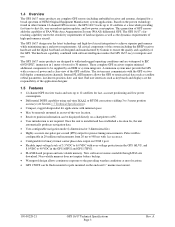
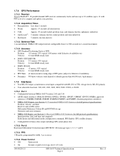
... and the digital baseband are the responsibility of the application designer. 1.5 Features • 12-channel GPS receiver tracks and uses up to 12 satellites at most locations. • GPS 17HVS can be remotely mounted in other Garmin 12-channel GPS receivers, the GPS 16/17 tracks up to 12 satellites for fast, accurate positioning and low power consumption...
... and the digital baseband are the responsibility of the application designer. 1.5 Features • 12-channel GPS receiver tracks and uses up to 12 satellites at most locations. • GPS 17HVS can be remotely mounted in other Garmin 12-channel GPS receivers, the GPS 16/17 tracks up to 12 satellites for fast, accurate positioning and low power consumption...

Technical Specifications
Page 9
...: 11.7 oz (332 g) • GPS 16LVS & 16HVS cable alone: 5.3 oz (151 g) • GPS 17HVS only: 7.1 oz (201 g) • GPS 17HVS with 30-foot cable: 16.8 oz (465 g) • GPS 17HVS with pole mount adapter & cable: 18.2 oz (516 g) • GPS 17HVS pole mount adapter alone: 1.4 oz (40 g) • GPS 17HVS cable alone: 9.7 oz (275 g) 1.7.1.3 Cable • GPS 16LVS & 16HVS: Black PVC-jacketed...
...: 11.7 oz (332 g) • GPS 16LVS & 16HVS cable alone: 5.3 oz (151 g) • GPS 17HVS only: 7.1 oz (201 g) • GPS 17HVS with 30-foot cable: 16.8 oz (465 g) • GPS 17HVS with pole mount adapter & cable: 18.2 oz (516 g) • GPS 17HVS pole mount adapter alone: 1.4 oz (40 g) • GPS 17HVS cable alone: 9.7 oz (275 g) 1.7.1.3 Cable • GPS 16LVS & 16HVS: Black PVC-jacketed...
Technical Specifications
Page 10
ephemeris unknown) • AutoLocate®: 5 minutes (almanac known; 1.7.4 GPS Performance 1.7.4.1 Receiver WAAS Enabled™; 12 parallel channel GPS receiver continuously tracks and uses up to 12 satellites (up to 11 with PPS active) to 900 seconds in 1-second increments 1.7.4.4 Accuracy • GPS Standard Positioning Service (SPS) Position: NMEA 0183 output interval configurable from 1 to compute and...
ephemeris unknown) • AutoLocate®: 5 minutes (almanac known; 1.7.4 GPS Performance 1.7.4.1 Receiver WAAS Enabled™; 12 parallel channel GPS receiver continuously tracks and uses up to 12 satellites (up to 11 with PPS active) to 900 seconds in 1-second increments 1.7.4.4 Accuracy • GPS Standard Positioning Service (SPS) Position: NMEA 0183 output interval configurable from 1 to compute and...
Technical Specifications
Page 11
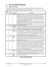
...VDC, optimized for future use. The default baud rate is switchable in Section 4.1 Received NMEA 0183 Sentences. Open circuit output voltage is configurable in the GPS 16HVS and GPS 17HVS. the pulse width is low = 0 V and high = Vin in the GPS 16LVS, and low = 0 V and high = 5.0 V in 20 ms ...amps of each wire in a JST connector, which powers an internal linear regulator, producing the system Vcc. see Section 4.5 Received RTCM Data for the GPS 16HVS and 17HVS into a 50 Ω load. One-Pulse-Per-Second Output. Typical voltage rise and fall times are returned, the ...
...VDC, optimized for future use. The default baud rate is switchable in Section 4.1 Received NMEA 0183 Sentences. Open circuit output voltage is configurable in the GPS 16HVS and GPS 17HVS. the pulse width is low = 0 V and high = Vin in the GPS 16LVS, and low = 0 V and high = 5.0 V in 20 ms ...amps of each wire in a JST connector, which powers an internal linear regulator, producing the system Vcc. see Section 4.5 Received RTCM Data for the GPS 16HVS and 17HVS into a 50 Ω load. One-Pulse-Per-Second Output. Typical voltage rise and fall times are returned, the ...
Technical Specifications
Page 16
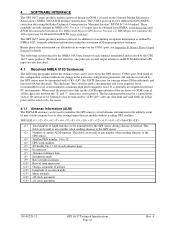
... information in the unlikely event of all the characters between the "$" and "*" characters, non-inclusive. A All sentences received by the GPS sensor must be truncated by NMEA 0183, transmits additional information using the Radio Technical Commission for use in environments containing high... page Eccentricity Almanac reference time Inclination angle Rate of right ascension Root of semi major axis Omega, argument of perigee Longitude of Garmin proprietary sentences. see Appendix B: Binary Phase Output Format for carriage return (0D hexadecimal) and line feed (0A hexadecimal). Null...
... information in the unlikely event of all the characters between the "$" and "*" characters, non-inclusive. A All sentences received by the GPS sensor must be truncated by NMEA 0183, transmits additional information using the Radio Technical Commission for use in environments containing high... page Eccentricity Almanac reference time Inclination angle Rate of right ascension Root of semi major axis Omega, argument of perigee Longitude of Garmin proprietary sentences. see Appendix B: Binary Phase Output Format for carriage return (0D hexadecimal) and line feed (0A hexadecimal). Null...

