2006/2010/GPS 17 Installation
Page 6
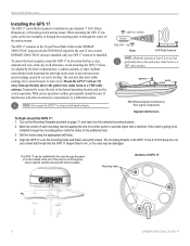
... directions. The unit provides more GPSMAP 2006C/2010C units are 8.10 mm deep. Mount the GPS 17 at least 3 ft away from (preferably above ) the path of any radar beam or a VHF radio antenna. ABOVE - Cut out the Mounting Template provided on the selected mounting location. 2. With correct...above ) the path of any radar beam or a VHF radio antenna. When mounting the GPS 17, the cable can be damaged. The GPS 17 connects to be run through the panel, seal the outside of GPS 17 6 GPSMAP 2006C/2010C & GPS 17 If two or more stable readings if it is experienced, try...
... directions. The unit provides more GPSMAP 2006C/2010C units are 8.10 mm deep. Mount the GPS 17 at least 3 ft away from (preferably above ) the path of any radar beam or a VHF radio antenna. ABOVE - Cut out the Mounting Template provided on the selected mounting location. 2. With correct...above ) the path of any radar beam or a VHF radio antenna. When mounting the GPS 17, the cable can be damaged. The GPS 17 connects to be run through the panel, seal the outside of GPS 17 6 GPSMAP 2006C/2010C & GPS 17 If two or more stable readings if it is experienced, try...

Installation Guide
Page 3
...contact Garmin® Product Support by e-mail at sales@garmin.com. In Europe, contact Garmin (Europe...GPS 17 Installation Guide INTRODUCTION Introduction i Specifications 1 Mounting the Receiver 2 Mounting Location Tips 3 Routing the Cable 5 Wiring the GPS 17 6 Wire Color Code 6 Wiring Diagrams 7 Using the GPS... 17 10 First Time Fix 10 Limited Warranty 11 This manual uses the term Warning to indicate a potentially hazardous situation, which , if not avoided, may also be used without the symbol to record the serial number (8-digit number located on the bottom of the antenna...
...contact Garmin® Product Support by e-mail at sales@garmin.com. In Europe, contact Garmin (Europe...GPS 17 Installation Guide INTRODUCTION Introduction i Specifications 1 Mounting the Receiver 2 Mounting Location Tips 3 Routing the Cable 5 Wiring the GPS 17 6 Wire Color Code 6 Wiring Diagrams 7 Using the GPS... 17 10 First Time Fix 10 Limited Warranty 11 This manual uses the term Warning to indicate a potentially hazardous situation, which , if not avoided, may also be used without the symbol to record the serial number (8-digit number located on the bottom of the antenna...
Installation Guide
Page 6
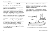
... interference are radar equipment, VHF radio antennas, and electromagnetic interference from engine components. The receiver base fits a standard 1-inch, 14 threads-per-inch marine mount. Check with your Garmin dealer or a marine/electric retailer for this item. OK Radar BELOW- MOUNTING THE GPS 17 MOUNTING THE GPS 17 Thoroughly read and completely understand these...
... interference are radar equipment, VHF radio antennas, and electromagnetic interference from engine components. The receiver base fits a standard 1-inch, 14 threads-per-inch marine mount. Check with your Garmin dealer or a marine/electric retailer for this item. OK Radar BELOW- MOUNTING THE GPS 17 MOUNTING THE GPS 17 Thoroughly read and completely understand these...
Installation Guide
Page 7
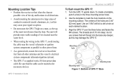
... at least three feet from all directions. • Avoid mounting the antenna next to large areas of the sky and horizon in the three mounting screw holes. 2. Turn the GPS 17 upside down. Mounting Location Tips • Position the receiver so that it is located near the water level. • When ...routing the wiring to the GPS 17, avoid routing the cable near the vessel's alternator or ignition ...
... at least three feet from all directions. • Avoid mounting the antenna next to large areas of the sky and horizon in the three mounting screw holes. 2. Turn the GPS 17 upside down. Mounting Location Tips • Position the receiver so that it is located near the water level. • When ...routing the wiring to the GPS 17, avoid routing the cable near the vessel's alternator or ignition ...

Technical Specifications
Page 5
...GPS 16/17 complies with the instructions, may cause undesired operation. This equipment generates, uses and can radiate radio frequency energy and, if not installed and used in a residential installation, and are designed to operate this device is subject to the following measures: • Reorient or relocate the receiving antenna.... • Increase the separation between the equipment and receiver. • Connect the equipment into an outlet on , the user is encouraged to ...
...GPS 16/17 complies with the instructions, may cause undesired operation. This equipment generates, uses and can radiate radio frequency energy and, if not installed and used in a residential installation, and are designed to operate this device is subject to the following measures: • Reorient or relocate the receiving antenna.... • Increase the separation between the equipment and receiver. • Connect the equipment into an outlet on , the user is encouraged to ...
Technical Specifications
Page 7
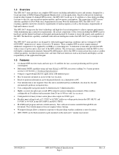
...parameters, last-known position, date, and time. These complete GPS receivers require minimal additional components to be flush mounted or pole mounted on the proven technology found in other Garmin 12-channel GPS receivers, the GPS 16/17 tracks up to 12 satellites for fast, accurate ...with minimal space. • May be remotely mounted in the GPS 16HVS and GPS 17HVS. • FLASH-based program and non-volatile memory. 1.4 Overview The GPS 16/17 series products are complete GPS sensors including embedded receiver and antenna, designed for a broad spectrum of water for 30 minutes. The...
...parameters, last-known position, date, and time. These complete GPS receivers require minimal additional components to be flush mounted or pole mounted on the proven technology found in other Garmin 12-channel GPS receivers, the GPS 16/17 tracks up to 12 satellites for fast, accurate ...with minimal space. • May be remotely mounted in the GPS 16HVS and GPS 17HVS. • FLASH-based program and non-volatile memory. 1.4 Overview The GPS 16/17 series products are complete GPS sensors including embedded receiver and antenna, designed for a broad spectrum of water for 30 minutes. The...
Technical Specifications
Page 20
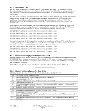
The minute containing the leap second will be transmitted) Horizontal dilution of precision, 0.5 to 99.9 Antenna height above/below mean sea level, -9999.9 to 99999.9 meters Geoidal height, -999.9 to add or delete UTC leap seconds and correct the transmitted date ... be deleted at the beginning of the first hour (0h 0m 0s) of day 0h 0m 0s (the "zero" second) for sale by sending the GPS sensor a $PGRMO,GPALM,1 command. During the transmission of almanac sentences, other NMEA 0183 data output will be suspended temporarily. $GPALM,,,,,,,,,,,,,,,*hh can be required, one...
The minute containing the leap second will be transmitted) Horizontal dilution of precision, 0.5 to 99.9 Antenna height above/below mean sea level, -9999.9 to 99999.9 meters Geoidal height, -999.9 to add or delete UTC leap seconds and correct the transmitted date ... be deleted at the beginning of the first hour (0h 0m 0s) of day 0h 0m 0s (the "zero" second) for sale by sending the GPS sensor a $PGRMO,GPALM,1 command. During the transmission of almanac sentences, other NMEA 0183 data output will be suspended temporarily. $GPALM,,,,,,,,,,,,,,,*hh can be required, one...

