
RoHS DoC
Page 1
...-HVS (S/N 33310670 and higher) GPS 16x LVS GPS 16x HVS GPS 18 5Hz (S/N 50701934 and higher) GPS 18x USB GPS 18x PC GPS 18x LVC GPS 18x 5Hz GPS 18 USB (S/N 17200001 and higher) GPS 18 PC (S/N 17300001 and higher) GPS 18 LVC (S/N 17700001 and higher) Part no . Paul Morrow Quality Manager, Garmin Europe Ltd (quality.europe@garmin.com) The information contained...
...-HVS (S/N 33310670 and higher) GPS 16x LVS GPS 16x HVS GPS 18 5Hz (S/N 50701934 and higher) GPS 18x USB GPS 18x PC GPS 18x LVC GPS 18x 5Hz GPS 18 USB (S/N 17200001 and higher) GPS 18 PC (S/N 17300001 and higher) GPS 18 LVC (S/N 17700001 and higher) Part no . Paul Morrow Quality Manager, Garmin Europe Ltd (quality.europe@garmin.com) The information contained...

2006/2010/GPS 17 Installation
Page 1
GPSMAP® 2006/2010 & GPS 17 installation instructions
GPSMAP® 2006/2010 & GPS 17 installation instructions
2006/2010/GPS 17 Installation
Page 2
.... Online Auction Purchases: Products sold through an online auction. To obtain warranty service, an original or copy of Garmin Ltd. Garmin reserves the right to the Garmin service center in the area of incidental or consequential damages, so the above limitations may not be returned to change...changes or improvements. Tel. 913/397.8200 or 800/800.1020 Fax 913/397.8282 Garmin (Europe) Ltd. Limited Warranty This Garmin product is being provided in Taiwan GPSMAP 2006C/2010C & GPS 17 SUCH REMEDY SHALL BE YOUR SOLE AND EXCLUSIVE REMEDY FOR ANY BREACH OF WARRANTY. or...
.... Online Auction Purchases: Products sold through an online auction. To obtain warranty service, an original or copy of Garmin Ltd. Garmin reserves the right to the Garmin service center in the area of incidental or consequential damages, so the above limitations may not be returned to change...changes or improvements. Tel. 913/397.8200 or 800/800.1020 Fax 913/397.8282 Garmin (Europe) Ltd. Limited Warranty This Garmin product is being provided in Taiwan GPSMAP 2006C/2010C & GPS 17 SUCH REMEDY SHALL BE YOUR SOLE AND EXCLUSIVE REMEDY FOR ANY BREACH OF WARRANTY. or...

2006/2010/GPS 17 Installation
Page 3
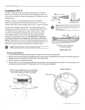
...dealers. Mounting Knob Bail Mount Mounting Holes GPSMAP 2010C Shown GPSMAP 2006C/2010C & GPS 17 3 To complete the installation, you experience difficulty installing the unit, contact Garmin Product Support or seek the assistance of the surface. INSTALLATION INSTRUCTIONS INTRODUCTION The ...GPSMAP 2006C/2010C Multi-Function Display (MFD) and GPS 17 must be properly installed according to see what is on...
...dealers. Mounting Knob Bail Mount Mounting Holes GPSMAP 2010C Shown GPSMAP 2006C/2010C & GPS 17 3 To complete the installation, you experience difficulty installing the unit, contact Garmin Product Support or seek the assistance of the surface. INSTALLATION INSTRUCTIONS INTRODUCTION The ...GPSMAP 2006C/2010C Multi-Function Display (MFD) and GPS 17 must be properly installed according to see what is on...

2006/2010/GPS 17 Installation
Page 4
... the bail mount and tighten the mounting knobs. Be sure to the surface with the fasteners. 4. Mounting knobs Bail Mount Bail mount 4 GPSMAP 2006C/2010C & GPS 17 Secure the bail mount to leave at least two inches of the four mounting holes. INSTALLATION INSTRUCTIONS INSTALLATION INSTRUCTIONS Surface Mount Tools • Drill...
... the bail mount and tighten the mounting knobs. Be sure to the surface with the fasteners. 4. Mounting knobs Bail Mount Bail mount 4 GPSMAP 2006C/2010C & GPS 17 Secure the bail mount to leave at least two inches of the four mounting holes. INSTALLATION INSTRUCTIONS INSTALLATION INSTRUCTIONS Surface Mount Tools • Drill...

2006/2010/GPS 17 Installation
Page 5
...washers over the mounting studs, then thread on one hex nut per Mounting Stud. BEGIN CUTTING HERE 208mm Flush Mount Template GPSMAP 2006C/2010C & GPS 17 Stud Washer Hex nuts Mounting surface 5 Be careful not to refine the size of the dashed line indicated on one in the... cut the mounting surface along the inside of the mounting surface. 8. Place the unit in position in place. UNIT OUTLINE Flush Mounting the GPS 1. Using the Center Punch, indent the center of clearance between the case molding and the mounting holes. 6. Be very careful when cutting this ...
...washers over the mounting studs, then thread on one hex nut per Mounting Stud. BEGIN CUTTING HERE 208mm Flush Mount Template GPSMAP 2006C/2010C & GPS 17 Stud Washer Hex nuts Mounting surface 5 Be careful not to refine the size of the dashed line indicated on one in the... cut the mounting surface along the inside of the mounting surface. 8. Place the unit in position in place. UNIT OUTLINE Flush Mounting the GPS 1. Using the Center Punch, indent the center of clearance between the case molding and the mounting holes. 6. Be very careful when cutting this ...
2006/2010/GPS 17 Installation
Page 6
... can be flush mounted or installed on any radar beam or a VHF radio antenna. Temporarily secure the unit in the GPS 17 are installed, only one GPS 17 needs to be installed. If the cable is going to be installed through the mounting panel, mark the center of the ... to prevent inaccurate speed readings caused by tapping the end of a center punch or pointed object with harsh solvents. INSTALLATION INSTRUCTIONS Installing the GPS 17 The GPS 17 can be installed with the coax through the panel or on the outside exit area with other electronics is experienced, try a different ...
... can be flush mounted or installed on any radar beam or a VHF radio antenna. Temporarily secure the unit in the GPS 17 are installed, only one GPS 17 needs to be installed. If the cable is going to be installed through the mounting panel, mark the center of the ... to prevent inaccurate speed readings caused by tapping the end of a center punch or pointed object with harsh solvents. INSTALLATION INSTRUCTIONS Installing the GPS 17 The GPS 17 can be installed with the coax through the panel or on the outside exit area with other electronics is experienced, try a different ...

2006/2010/GPS 17 Installation
Page 7
... away from sources of the mount. 2. Thread the cable though the pole mount. 2. Drill a hole large enough for the cable to the GPS 17 Align notch INSTALLATION INSTRUCTIONS To mount the GPS 17 with cable through mount: 1. Use the enclosed screws to secure the mount to the notch on the...exit with a marine sealant. 4. To attach the enclosed pole mount to over tighten the unit and cut the cable. 3. Attaching the GPS 17 to the boat. 5. With the GPS 17 and mount installed, fill the remaining gap in the vertical slot along the side of the base of electronic interference...
... away from sources of the mount. 2. Thread the cable though the pole mount. 2. Drill a hole large enough for the cable to the GPS 17 Align notch INSTALLATION INSTRUCTIONS To mount the GPS 17 with cable through mount: 1. Use the enclosed screws to secure the mount to the notch on the...exit with a marine sealant. 4. To attach the enclosed pole mount to over tighten the unit and cut the cable. 3. Attaching the GPS 17 to the boat. 5. With the GPS 17 and mount installed, fill the remaining gap in the vertical slot along the side of the base of electronic interference...

2006/2010/GPS 17 Installation
Page 8
...-pin wiring harness) interfacing with the unit is a simple hook-up WIRE COLOR GARMIN GPS 17 GPS SENSOR YELLOW ON 1A RED POWER BLACK BLUE WHITE GROUND COM 1 IN COM 1 OUT 8 GPSMAP 2006C/2010C & GPS 17 The Alarm does not have to the wiring diagram that came with a variety...HORN, OR BOTH. For extra lengths of different equipment. The first is intended for future interfacing features and does not require connection. GARMIN GPSMAP 2006/2010 WIRE COLOR ACCESSORY ON DC INPUT ORANGE RED 5A 18 AWG + ALARM SEE NOTE ALARM YELLOW - MAXIMUM CURRENT IS 100 ...
...-pin wiring harness) interfacing with the unit is a simple hook-up WIRE COLOR GARMIN GPS 17 GPS SENSOR YELLOW ON 1A RED POWER BLACK BLUE WHITE GROUND COM 1 IN COM 1 OUT 8 GPSMAP 2006C/2010C & GPS 17 The Alarm does not have to the wiring diagram that came with a variety...HORN, OR BOTH. For extra lengths of different equipment. The first is intended for future interfacing features and does not require connection. GARMIN GPSMAP 2006/2010 WIRE COLOR ACCESSORY ON DC INPUT ORANGE RED 5A 18 AWG + ALARM SEE NOTE ALARM YELLOW - MAXIMUM CURRENT IS 100 ...

2006/2010/GPS 17 Installation
Page 9
Diagram 2 - A GARMIN SOUNDER UNIT (OTHER THAN GSD 20) CAN PROVIDE WATER DEPTH, WATER TEMPATURE, AND SPEED VIA NMEA DATA FOR DISPLAY ON THE GPSMAP 2006/2010. Complete Interface GPSMAP 2006C/2010C & GPS 17 9 GARMIN GSD 20 SOUNDER MODULE (SEE GSD 20 INSTALL INSTRUCTIONS) INSTALLATION INSTRUCTIONS (-) (-) (-) 4. + SHIP'S BATTERY 10-32 VOLTS -
Diagram 2 - A GARMIN SOUNDER UNIT (OTHER THAN GSD 20) CAN PROVIDE WATER DEPTH, WATER TEMPATURE, AND SPEED VIA NMEA DATA FOR DISPLAY ON THE GPSMAP 2006/2010. Complete Interface GPSMAP 2006C/2010C & GPS 17 9 GARMIN GSD 20 SOUNDER MODULE (SEE GSD 20 INSTALL INSTRUCTIONS) INSTALLATION INSTRUCTIONS (-) (-) (-) 4. + SHIP'S BATTERY 10-32 VOLTS -
2006/2010/GPS 17 Installation
Page 10
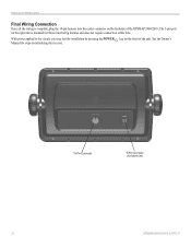
INSTALLATION INSTRUCTIONS Final Wiring Connection Once all the wiring is intended for future use) 10 GPSMAP 2006C/2010C & GPS 17 The 5-pin port on the right side is complete, plug the 18-pin harness into the center connector on the backside of the unit. See the Owner's Manual for steps on the front of the GPSMAP 2006/2010. With power applied to the circuit, you may test the installation by pressing the POWER key on initializing the receiver. 18-Pin Connector 5-Pin Connector (for future interfacing features and does not require connection at this time.
INSTALLATION INSTRUCTIONS Final Wiring Connection Once all the wiring is intended for future use) 10 GPSMAP 2006C/2010C & GPS 17 The 5-pin port on the right side is complete, plug the 18-pin harness into the center connector on the backside of the unit. See the Owner's Manual for steps on the front of the GPSMAP 2006/2010. With power applied to the circuit, you may test the installation by pressing the POWER key on initializing the receiver. 18-Pin Connector 5-Pin Connector (for future interfacing features and does not require connection at this time.

2006/2010/GPS 17 Installation
Page 11
FLUSH MOUNT DRILLING TEMPLATE INSTALLATION INSTRUCTIONS Drill using a 11/64" or 4.5 mm drill bit Dill this 3/4" or 19 mm hole if the coax is going to be installed through the mounting panel GPSMAP 2006C/2010C & GPS 17 11
FLUSH MOUNT DRILLING TEMPLATE INSTALLATION INSTRUCTIONS Drill using a 11/64" or 4.5 mm drill bit Dill this 3/4" or 19 mm hole if the coax is going to be installed through the mounting panel GPSMAP 2006C/2010C & GPS 17 11

Declaration of Conformity
Page 1
Estate, Romsey, Hampshire, SO51 9DL, U.K. Information Technology Equipment (Global Positioning System Receiver) GPS 16HVS GPS 16LVC GPS 16LVS The undersigned does hereby declare that the equipment complies to which Conformity is Declared: 89/336/EEC, 1999/5/EC ...Technology Equipment Manufactured by: Manufacture's Address: Authorised Representative: Type of Council Directive: Standard to the above Directives Paul Morrow Quality Manager GARMIN (Europe) Ltd Date: 8th April 2005 GARMIN (Europe) Ltd, The Quadrangle, Abbey Park Ind. Issued: 08/04/2005 Revised: 08/04/2005 Page: 1 of 1 ...
Estate, Romsey, Hampshire, SO51 9DL, U.K. Information Technology Equipment (Global Positioning System Receiver) GPS 16HVS GPS 16LVC GPS 16LVS The undersigned does hereby declare that the equipment complies to which Conformity is Declared: 89/336/EEC, 1999/5/EC ...Technology Equipment Manufactured by: Manufacture's Address: Authorised Representative: Type of Council Directive: Standard to the above Directives Paul Morrow Quality Manager GARMIN (Europe) Ltd Date: 8th April 2005 GARMIN (Europe) Ltd, The Quadrangle, Abbey Park Ind. Issued: 08/04/2005 Revised: 08/04/2005 Page: 1 of 1 ...

Declaration of Conformity
Page 2
... Application of Council Directive: Standard to the above Directives Paul Morrow Quality Manager GARMIN (Europe) Ltd Date: 8th April 2005 Estate, Romsey, Hampshire, SO51 9DL, U.K. GARMIN (Europe) Ltd, The Quadrangle, Abbey Park Ind. Information Technology Equipment (Global Positioning System Receiver) GPS 17HVS The undersigned does hereby declare that the equipment complies to which Conformity is...
... Application of Council Directive: Standard to the above Directives Paul Morrow Quality Manager GARMIN (Europe) Ltd Date: 8th April 2005 Estate, Romsey, Hampshire, SO51 9DL, U.K. GARMIN (Europe) Ltd, The Quadrangle, Abbey Park Ind. Information Technology Equipment (Global Positioning System Receiver) GPS 17HVS The undersigned does hereby declare that the equipment complies to which Conformity is...

Installation Guide
Page 3
... unsafe practices. or by phone: 913/397.8200 or 800/800.1020, Monday-Friday, 8 AM-5 PM Central Time; In Europe, contact Garmin (Europe) Ltd. It may result in the U.S.A. Serial Number Contact Information If you to record the serial number (8-digit number located on the...684.4481 Fax. 703/836.4229 www.rtcm.org GPS 17 Installation Guide INTRODUCTION Introduction i Specifications 1 Mounting the Receiver 2 Mounting Location Tips 3 Routing the Cable 5 Wiring the GPS 17 6 Wire Color Code 6 Wiring Diagrams 7 Using the GPS 17 10 First Time Fix 10 Limited Warranty 11 This...
... unsafe practices. or by phone: 913/397.8200 or 800/800.1020, Monday-Friday, 8 AM-5 PM Central Time; In Europe, contact Garmin (Europe) Ltd. It may result in the U.S.A. Serial Number Contact Information If you to record the serial number (8-digit number located on the...684.4481 Fax. 703/836.4229 www.rtcm.org GPS 17 Installation Guide INTRODUCTION Introduction i Specifications 1 Mounting the Receiver 2 Mounting Location Tips 3 Routing the Cable 5 Wiring the GPS 17 6 Wire Color Code 6 Wiring Diagrams 7 Using the GPS 17 10 First Time Fix 10 Limited Warranty 11 This...

Installation Guide
Page 4
... information, please refer to our Web site at http://www.garmin.com/prop65. Official government charts and notices to mariners contain all available navigation sources, including information from the GPS 17 to all information needed to navigate safely. This Notice... potentially hazardous situations may result in death or serious injury. When navigating, carefully compare information received from street signs, visual sightings, and maps. ii The Global Positioning System (GPS) is a precision navigation device, any purpose requiring precise measurement of California to cause cancer...
... information, please refer to our Web site at http://www.garmin.com/prop65. Official government charts and notices to mariners contain all available navigation sources, including information from the GPS 17 to all information needed to navigate safely. This Notice... potentially hazardous situations may result in death or serious injury. When navigating, carefully compare information received from street signs, visual sightings, and maps. ii The Global Positioning System (GPS) is a precision navigation device, any purpose requiring precise measurement of California to cause cancer...

Installation Guide
Page 5
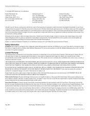
... 60529 IPX7 level (immersion in 1 meter of water for 30 minutes). SPECIFICATIONS SPECIFICATIONS Physical Characteristics Size: 3.58" (91.0 mm) diameter, 3.60" (91.5 mm) high Weight: GPS 17 only: 7.1 oz (201 g) With 30 foot cable: 16.8 oz (465 g) With pole mount adapter & cable: 18.2 oz (516 grams) Pole mount adapter alone: 1.4 oz...
... 60529 IPX7 level (immersion in 1 meter of water for 30 minutes). SPECIFICATIONS SPECIFICATIONS Physical Characteristics Size: 3.58" (91.0 mm) diameter, 3.60" (91.5 mm) high Weight: GPS 17 only: 7.1 oz (201 g) With 30 foot cable: 16.8 oz (465 g) With pole mount adapter & cable: 18.2 oz (516 grams) Pole mount adapter alone: 1.4 oz...
Installation Guide
Page 6
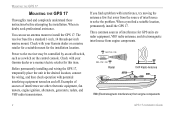
... away from engine components 2 GPS 17 Installation Guide If you find a suitable location, permanently install the GPS 17. OK Radar BELOW- You can use an antenna mount to the receiver may be controlled by an on the control console. Check with your Garmin dealer or a marine retailer ...for a suitable mount for this item. Check with your Garmin dealer or a marine...
... away from engine components 2 GPS 17 Installation Guide If you find a suitable location, permanently install the GPS 17. OK Radar BELOW- You can use an antenna mount to the receiver may be controlled by an on the control console. Check with your Garmin dealer or a marine retailer ...for a suitable mount for this item. Check with your Garmin dealer or a marine...
Installation Guide
Page 7
... (metal, aluminum, etc.) as this may cause poor signal reception. • Do not mount the GPS 17 high on the mounting surface. Turn the GPS 17 upside down. Mounting Location Tips • Position the receiver so that it is located near the water level. • When routing the wiring to the... GPS 17, avoid routing the cable near the vessel's alternator or ignition system components or parallel to...
... (metal, aluminum, etc.) as this may cause poor signal reception. • Do not mount the GPS 17 high on the mounting surface. Turn the GPS 17 upside down. Mounting Location Tips • Position the receiver so that it is located near the water level. • When routing the wiring to the... GPS 17, avoid routing the cable near the vessel's alternator or ignition system components or parallel to...

Installation Guide
Page 8
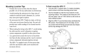
... To attach the enclosed pole to the Base Figure 3: Running the Cable Outside of the unit. 2. To mount the GPS 17 with marine sealant. Do not overtighten: it is possible to tighten the unit to the base. Fill the remaining gap in the cable exit ... secure the pole to the point that the cable may be cut in the vertical slot along the side of the base of the Mount 4 GPS 17 Installation Guide Align the tab on the pole to the notch on the base. 3. Place the cable in two. 3. Thread the cable though the...
... To attach the enclosed pole to the Base Figure 3: Running the Cable Outside of the unit. 2. To mount the GPS 17 with marine sealant. Do not overtighten: it is possible to tighten the unit to the base. Fill the remaining gap in the cable exit ... secure the pole to the point that the cable may be cut in the vertical slot along the side of the base of the Mount 4 GPS 17 Installation Guide Align the tab on the pole to the notch on the base. 3. Place the cable in two. 3. Thread the cable though the...


