Installation Instructions
Page 1
... Network Connector: • Knife • Pliers • 15 mm wrench • AMP modular-plug hand tool and die set or compatible equivalent December 2010 190-01266-02 Rev. In the UK, contact Garmin (Europe) Ltd. Before installing your GMR 400/600/1200 xHD radar, confirm that the radar is turned off or the DC power input is harmful. Product Registration Help us better support...
... Network Connector: • Knife • Pliers • 15 mm wrench • AMP modular-plug hand tool and die set or compatible equivalent December 2010 190-01266-02 Rev. In the UK, contact Garmin (Europe) Ltd. Before installing your GMR 400/600/1200 xHD radar, confirm that the radar is turned off or the DC power input is harmful. Product Registration Help us better support...
Installation Instructions
Page 2
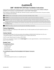
... above head height). Selecting a Location When selecting a location to 7 ft. (2 m). 2 GMR 400/600/1200 xHD Installation Instructions Obstructions in the path of the radar beam may be sturdy enough to support the weight of a radar beam. IEC 60936-1 clause 3-27.1 states maximum distances from lights. • The mounting surface or platform should be used as possible, and parallel with the water line. • Garmin recommends mounting the radar...
... above head height). Selecting a Location When selecting a location to 7 ft. (2 m). 2 GMR 400/600/1200 xHD Installation Instructions Obstructions in the path of the radar beam may be sturdy enough to support the weight of a radar beam. IEC 60936-1 clause 3-27.1 states maximum distances from lights. • The mounting surface or platform should be used as possible, and parallel with the water line. • Garmin recommends mounting the radar...

Installation Instructions
Page 3
... 4 GMR 400/600/1200 xHD Installation Instructions Figure 5 Figure 6 flat washer spring washer M10 hex nut 3 To adjust the Front of Boat Offset on the front of pedestal by loosening the screw and lifting the hatch off of Boat Offset setting on the Mounting Template (Option A or Option B). The Mounting Template has two hole patterns: Option A and Option B. Hoist the radar into position using a pre-drilled Garmin compatible Furuno...
... 4 GMR 400/600/1200 xHD Installation Instructions Figure 5 Figure 6 flat washer spring washer M10 hex nut 3 To adjust the Front of Boat Offset on the front of pedestal by loosening the screw and lifting the hatch off of Boat Offset setting on the Mounting Template (Option A or Option B). The Mounting Template has two hole patterns: Option A and Option B. Hoist the radar into position using a pre-drilled Garmin compatible Furuno...
Installation Instructions
Page 4
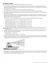
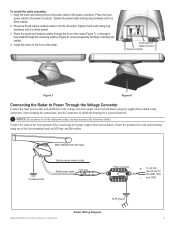
... deck. Garmin provides a rubber cable grommet to create a custom-length Garmin Marine Network cable if needed (see page 8). 4 GMR 400/600/1200 xHD Installation Instructions Align the 3. When installing the voltage converter unit, consider the following : • To ensure safety, use the supplied heat-shrink butt connectors. GMR 400/600/1200 xHD Voltage Converter Unit + Sample boat fuse block To radar Voltage Converter Unit To power - 15 A slow-blow fuse To RF ground Connecting the Voltage Converter to a Boat Fuse Block 10...
... deck. Garmin provides a rubber cable grommet to create a custom-length Garmin Marine Network cable if needed (see page 8). 4 GMR 400/600/1200 xHD Installation Instructions Align the 3. When installing the voltage converter unit, consider the following : • To ensure safety, use the supplied heat-shrink butt connectors. GMR 400/600/1200 xHD Voltage Converter Unit + Sample boat fuse block To radar Voltage Converter Unit To power - 15 A slow-blow fuse To RF ground Connecting the Voltage Converter to a Boat Fuse Block 10...
Installation Instructions
Page 5
... until it is firmly sealed.. 2. After crimping the connections, heat the connectors to the voltage converter output cable (red and black) using one of the radar. and 1206) To RF ground Power Wiring Diagram GMR 400/600/1200 xHD Installation Instructions 5 Press the RJ-45 marine network cable to cut the radar power cable, you must reconnect the in-line fuse holder. Tighten the power-cable locking ring clockwise until it is firmly sealed. 3. Notice...
... until it is firmly sealed.. 2. After crimping the connections, heat the connectors to the voltage converter output cable (red and black) using one of the radar. and 1206) To RF ground Power Wiring Diagram GMR 400/600/1200 xHD Installation Instructions 5 Press the RJ-45 marine network cable to cut the radar power cable, you must reconnect the in-line fuse holder. Tighten the power-cable locking ring clockwise until it is firmly sealed. 3. Notice...
Installation Instructions
Page 6
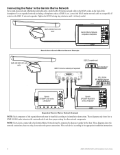
... to its installation instructions. GMR 400/600/1200 xHD radar Garmin Marine Networkcompatible chartplotter GMR 400/600/1200 xHD radar Stand-Alone Garmin Marine Network Example GSD 22 sounder unit GMS 10 marine network port expander xxxx xxx To transducer xxxxxxxxxxxxxxxxxxxx GDL 30/30A XM weather receiver Garmin GPSMAP 3000 series chartplotter Garmin GPSMAP 4000/5000 series chartplotter Expanded Garmin Marine Network Example NOTE: Each component of the chartplotter. however, they do not show the network connections; Connecting the Radar to the Garmin Marine Network For...
... to its installation instructions. GMR 400/600/1200 xHD radar Garmin Marine Networkcompatible chartplotter GMR 400/600/1200 xHD radar Stand-Alone Garmin Marine Network Example GSD 22 sounder unit GMS 10 marine network port expander xxxx xxx To transducer xxxxxxxxxxxxxxxxxxxx GDL 30/30A XM weather receiver Garmin GPSMAP 3000 series chartplotter Garmin GPSMAP 4000/5000 series chartplotter Expanded Garmin Marine Network Example NOTE: Each component of the chartplotter. however, they do not show the network connections; Connecting the Radar to the Garmin Marine Network For...
Installation Instructions
Page 7
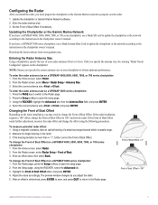
... in the chartplotter owner's manual. Update the chartplotter or Garmin Marine Network software. 2. Updating the Chartplotter or the Garmin Marine Network If you have a GPSMAP 4000, 5000, 6000, 7000, or 700 series chartplotter, use a blank SD card to update the chartplotter or the network according to properly use a blank Garmin Data Card to update the chartplotter or the network according to obtain optimum performance. If you have a GPSMAP 3000 series chartplotter, use the radar. 1. Entering the Radar Antenna Size Using a chartplotter, specify the size of Boat Offset slider...
... in the chartplotter owner's manual. Update the chartplotter or Garmin Marine Network software. 2. Updating the Chartplotter or the Garmin Marine Network If you have a GPSMAP 4000, 5000, 6000, 7000, or 700 series chartplotter, use a blank SD card to update the chartplotter or the network according to properly use a blank Garmin Data Card to update the chartplotter or the network according to obtain optimum performance. If you have a GPSMAP 3000 series chartplotter, use the radar. 1. Entering the Radar Antenna Size Using a chartplotter, specify the size of Boat Offset slider...
Installation Instructions
Page 8
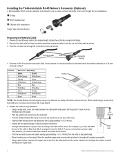
Installing the Field-Installable RJ-45 Network Connector (Optional) A field-installable RJ-45 network connector is provided for you to the desired length. Retain the cut any of pliers, squeeze the copper tape to avoid damaging the copper tape. 8 GMR 400/600/1200 xHD Installation Instructions Note which cable side, A or B, was removed in proper order according to the edge of the jacket as shown...
Installing the Field-Installable RJ-45 Network Connector (Optional) A field-installable RJ-45 network connector is provided for you to the desired length. Retain the cut any of pliers, squeeze the copper tape to avoid damaging the copper tape. 8 GMR 400/600/1200 xHD Installation Instructions Note which cable side, A or B, was removed in proper order according to the edge of the jacket as shown...
Installation Instructions
Page 9
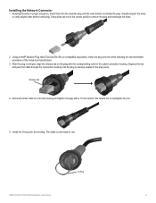
Installing the Network Connector 1. If any wires are not in proper sequence, insert them into the modular plug until the plug is now ready to use. Be careful not to verify proper order before continuing. O-Ring GMR 400/600/1200 xHD Installation Instructions 9 Keeping the wires in the correct position, remove the plug and rearrange the wires... Using an AMP Modular Plug Hand Tool and Die Set (or compatible equivalent), crimp the plug onto the wires following the recommended procedure of the crimp-tool manufacturer. 3. Depress the tab and push the cable through the connection ...
Installing the Network Connector 1. If any wires are not in proper sequence, insert them into the modular plug until the plug is now ready to use. Be careful not to verify proper order before continuing. O-Ring GMR 400/600/1200 xHD Installation Instructions 9 Keeping the wires in the correct position, remove the plug and rearrange the wires... Using an AMP Modular Plug Hand Tool and Die Set (or compatible equivalent), crimp the plug onto the wires following the recommended procedure of the crimp-tool manufacturer. 3. Depress the tab and push the cable through the connection ...
Installation Instructions
Page 11
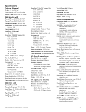
... Dual Range Mode: Simultaneous operation of two ranges displayed in split screen format User selectable ranges of 1/8 nm to 3 nm on left side and 1/8 nm to 72 nm on right side Timed Transmit: (GPSMAP 3000 series chartplotters) user-specified transmission and standby time. manual or auto (AFC) receiver tuning; Radar/Chart Overlay: Overlay mode is required) GMR 400/600/1200 xHD Installation Instructions 11 Sentry: (GPSMAP 4000/5000/6000/7000/700 series chartplotters) user-adjustable timedtransmit mode Zoom Mode: 2x, 4x (GPSMAP 3000 series chartplotters only...
... Dual Range Mode: Simultaneous operation of two ranges displayed in split screen format User selectable ranges of 1/8 nm to 3 nm on left side and 1/8 nm to 72 nm on right side Timed Transmit: (GPSMAP 3000 series chartplotters) user-specified transmission and standby time. manual or auto (AFC) receiver tuning; Radar/Chart Overlay: Overlay mode is required) GMR 400/600/1200 xHD Installation Instructions 11 Sentry: (GPSMAP 4000/5000/6000/7000/700 series chartplotters) user-adjustable timedtransmit mode Zoom Mode: 2x, 4x (GPSMAP 3000 series chartplotters only...
Installation Instructions
Page 12
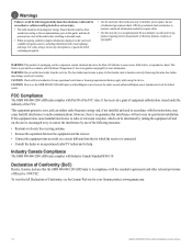
... installed and used in a particular installation. This Notice is connected. • Consult the dealer or an experienced radio/TV technician for any discrepancies or questions before switching to transmit mode. • When navigating, carefully compare information displayed on a circuit different from the red wire. WARNING: Do not cut the fuse holder from that the GMR 400/600/1200 xHD radar is encouraged to try to replace, the use...
... installed and used in a particular installation. This Notice is connected. • Consult the dealer or an experienced radio/TV technician for any discrepancies or questions before switching to transmit mode. • When navigating, carefully compare information displayed on a circuit different from the red wire. WARNING: Do not cut the fuse holder from that the GMR 400/600/1200 xHD radar is encouraged to try to replace, the use...
Installation Instructions
Page 13
... Garmin authorized dealer or call Garmin Product Support for any Garmin warranty service station. Garmin retains the exclusive right to repair or replace the unit or software or offer a full refund of the purchase price at no warranty as a travel aid and must be responsible for shipping instructions and an RMA tracking number. Distributor warranties are not accepted for two years from the date...
... Garmin authorized dealer or call Garmin Product Support for any Garmin warranty service station. Garmin retains the exclusive right to repair or replace the unit or software or offer a full refund of the purchase price at no warranty as a travel aid and must be responsible for shipping instructions and an RMA tracking number. Distributor warranties are not accepted for two years from the date...
Installation Instructions
Page 14
... a registered trademark of this manual may not be reproduced, copied, transmitted, disseminated, downloaded or stored in Taiwan Raymarine® is strictly prohibited. For the latest free software updates (excluding map data) throughout the life of Raymarine Limited. December 2010 © 2010 Garmin Ltd. B Printed in any storage medium, for current updates and supplemental information concerning the use and operation of Furuno Electric Co., Ltd...
... a registered trademark of this manual may not be reproduced, copied, transmitted, disseminated, downloaded or stored in Taiwan Raymarine® is strictly prohibited. For the latest free software updates (excluding map data) throughout the life of Raymarine Limited. December 2010 © 2010 Garmin Ltd. B Printed in any storage medium, for current updates and supplemental information concerning the use and operation of Furuno Electric Co., Ltd...

