Installation Manual
Page 4
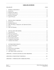
... Technical Specifications ...1-2 1.4 Reference Documents ...1-4 1.5 Limited Warranty...1-5 2 INSTALLATION OVERVIEW ...2-1 2.1 Introduction...2-1 2.2 Installation Materials ...2-1 2.3 GMA 240 Wiring, Configuration, and Adjustment Options 2-1 2.4 Noise ...2-5 2.5 GMA 240 Mounting ...2-6 3 INSTALLATION PROCEDURE...3-1 3.1 Unpacking Unit...3-1 3.2 Electrical Connections ...3-1 3.3 Audio Shield Termination ...3-2 3.4 GMA 240 Installation ...3-2 3.5 Post Installation Checkout ...3-3 3.6 Configuration Adjustments...3-4 3.7 Continued Airworthiness ...3-4 4 SYSTEM INTERCONNECTS ...4-1 4.1 Connector...
... Technical Specifications ...1-2 1.4 Reference Documents ...1-4 1.5 Limited Warranty...1-5 2 INSTALLATION OVERVIEW ...2-1 2.1 Introduction...2-1 2.2 Installation Materials ...2-1 2.3 GMA 240 Wiring, Configuration, and Adjustment Options 2-1 2.4 Noise ...2-5 2.5 GMA 240 Mounting ...2-6 3 INSTALLATION PROCEDURE...3-1 3.1 Unpacking Unit...3-1 3.2 Electrical Connections ...3-1 3.3 Audio Shield Termination ...3-2 3.4 GMA 240 Installation ...3-2 3.5 Post Installation Checkout ...3-3 3.6 Configuration Adjustments...3-4 3.7 Continued Airworthiness ...3-4 4 SYSTEM INTERCONNECTS ...4-1 4.1 Connector...
Installation Manual
Page 5
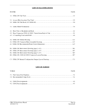
... 240 Outline Drawing ...A-1 A-2 GMA 240 Connector/Rack Assembly Drawing A-3 A-3 GMA 240 Recommended Panel Cutout Dimensions A-5 B-1 GMA 240 Interconnect Drawing (page 1 of 3 B-1 B-1 GMA 240 Interconnect Drawing (page 2 of 3 B-3 B-1 GMA 240 Interconnect Drawing (page 3 of 3 B-5 B-2 GMA 240, J2401 & J2402 Connector Layout Drawing B-7 C-1 GMA 240 Internal Configuration Jumper Layout Drawing C-1 LIST OF TABLES TABLE PAGE 3-1 Pin Contact Part Numbers...3-1 3-2 Recommended Crimp Tools ...3-1 4-1 J2401 Pin Assignments ...4-2 4-2 J2402 Pin Assignments ...4-3 GMA 240 Installation Manual...
... 240 Outline Drawing ...A-1 A-2 GMA 240 Connector/Rack Assembly Drawing A-3 A-3 GMA 240 Recommended Panel Cutout Dimensions A-5 B-1 GMA 240 Interconnect Drawing (page 1 of 3 B-1 B-1 GMA 240 Interconnect Drawing (page 2 of 3 B-3 B-1 GMA 240 Interconnect Drawing (page 3 of 3 B-5 B-2 GMA 240, J2401 & J2402 Connector Layout Drawing B-7 C-1 GMA 240 Internal Configuration Jumper Layout Drawing C-1 LIST OF TABLES TABLE PAGE 3-1 Pin Contact Part Numbers...3-1 3-2 Recommended Crimp Tools ...3-1 4-1 J2401 Pin Assignments ...4-2 4-2 J2402 Pin Assignments ...4-3 GMA 240 Installation Manual...

Installation Manual
Page 7
... cockpit light. Photocell dimming circuitry automatically adjusts the brightness of the unit. B Reference to GMA 240 throughout this manual refers to COM1 and a fail-safe warning audio input in the GMA 240 Pilot's Guide, P/N 190-00917-00. 1.2 Equipment Description The Garmin GMA 240 Audio Panel is controlled by the aircraft lighting bus. Information pertaining to the operation of the unit can be found in the event that power is interrupted or the unit is turned off. LED-illuminated push-button...
... cockpit light. Photocell dimming circuitry automatically adjusts the brightness of the unit. B Reference to GMA 240 throughout this manual refers to COM1 and a fail-safe warning audio input in the GMA 240 Pilot's Guide, P/N 190-00917-00. 1.2 Equipment Description The Garmin GMA 240 Audio Panel is controlled by the aircraft lighting bus. Information pertaining to the operation of the unit can be found in the event that power is interrupted or the unit is turned off. LED-illuminated push-button...
Installation Manual
Page 8
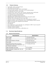
... COM audio source(s) when changing COM mic selection • MASQ™ Processing with configurable mute threshold • COM swap function • PTT indication • Power-off fail-safe to connect Pilot PTT, mic, and Headset to COM 1 if unit is turned off • Power-off fail-safe warning audio input • Full duplex Telephone interface • Front Panel Mini-Jack (MP3 player, cellular phone, etc.) 1.3 Technical Specifications 1.3.1 Physical...
... COM audio source(s) when changing COM mic selection • MASQ™ Processing with configurable mute threshold • COM swap function • PTT indication • Power-off fail-safe to connect Pilot PTT, mic, and Headset to COM 1 if unit is turned off • Power-off fail-safe warning audio input • Full duplex Telephone interface • Front Panel Mini-Jack (MP3 player, cellular phone, etc.) 1.3 Technical Specifications 1.3.1 Physical...
Installation Manual
Page 9
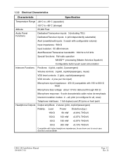
... noise de-emphasis Intercom isolation modes: 2 - 1.3.2 Electrical Characteristics Characteristic Specification Temperature Range -20°C to +55°C (operation) -55°C to +85°C (storage) Altitude 55,000 Feet Audio Panel Functions Dedicated Transceiver inputs: 3 (including TEL) Dedicated Receiver inputs: 4 (all , crew) Telephone interfaces: 1 full-duplex (use LRU pins or front jack) Headphone Outputs Output amplifiers: 2 stereo (pilot, copilot/passengers) Fidelity: Load Power Distortion (typ.) 150 Ω 50...
... noise de-emphasis Intercom isolation modes: 2 - 1.3.2 Electrical Characteristics Characteristic Specification Temperature Range -20°C to +55°C (operation) -55°C to +85°C (storage) Altitude 55,000 Feet Audio Panel Functions Dedicated Transceiver inputs: 3 (including TEL) Dedicated Receiver inputs: 4 (all , crew) Telephone interfaces: 1 full-duplex (use LRU pins or front jack) Headphone Outputs Output amplifiers: 2 stereo (pilot, copilot/passengers) Fidelity: Load Power Distortion (typ.) 150 Ω 50...
Installation Manual
Page 10
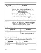
volume (typ.) Music input level: Characteristic Music Functions Front Panel MiniJack Functions Electrical Characteristics (continued) Specification Music inputs (stereo): 2 Music input impedance: 600 Ω (differential) Music gain: -20dB @ min volume, +26dB @ max.
volume (typ.) Music input level: Characteristic Music Functions Front Panel MiniJack Functions Electrical Characteristics (continued) Specification Music inputs (stereo): 2 Music input impedance: 600 Ω (differential) Music gain: -20dB @ min volume, +26dB @ max.
Installation Manual
Page 11
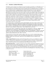
... warranty verification. Phone: 44/ (0) 870.8501241 FAX: 44/ (0) 870.850125 GMA 240 Installation Manual 190-00917-01 Page 1-5 Rev. or (v) damage to a product that are only valid in the area of intended distribution. Devices purchased in the United States or Canada must be returned to the Garmin service center in the United Kingdom, the United States, Canada, or Taiwan...
... warranty verification. Phone: 44/ (0) 870.8501241 FAX: 44/ (0) 870.850125 GMA 240 Installation Manual 190-00917-01 Page 1-5 Rev. or (v) damage to a product that are only valid in the area of intended distribution. Devices purchased in the United States or Canada must be returned to the Garmin service center in the United Kingdom, the United States, Canada, or Taiwan...

Installation Manual
Page 13
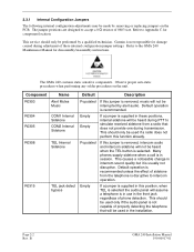
... interconnect wiring diagrams, mounting dimensions, and information pertaining to fit these options should be fabricated by the installing agency to installation. 2.2 Installation Materials 2.2.1 Equipment Available GMA 240 Audio Panel, Ship Level Assembly, P/N 010-00735-() includes the following sections: • Wiring options - B Section 2.3.2 GMA 240 Installation Manual 190-00917-01 Page 2-1 Rev. These configuration/adjustments are detailed in the following , depending on part number: Item Connector Kit, GMA 340 Rack Backplate, GMA 340 Unit Assembly, GMA 240 Audio Cables...
... interconnect wiring diagrams, mounting dimensions, and information pertaining to fit these options should be fabricated by the installing agency to installation. 2.2 Installation Materials 2.2.1 Equipment Available GMA 240 Audio Panel, Ship Level Assembly, P/N 010-00735-() includes the following sections: • Wiring options - B Section 2.3.2 GMA 240 Installation Manual 190-00917-01 Page 2-1 Rev. These configuration/adjustments are detailed in the following , depending on part number: Item Connector Kit, GMA 340 Rack Backplate, GMA 340 Unit Assembly, GMA 240 Audio Cables...
Installation Manual
Page 14
... a noticeable change in session. Page 2-2 Rev. If a jumper is supplied in the front jack regardless of phone detection. B GMA 240 Installation Manual 190-00917-01 Refer to Appendix C for damage caused during transmission. If this position, when TEL is selected the audio panel will assume a telephone is in use in these positions, internal sidetone will be heard during PTT to simulate received sidetone from...
... a noticeable change in session. Page 2-2 Rev. If a jumper is supplied in the front jack regardless of phone detection. B GMA 240 Installation Manual 190-00917-01 Refer to Appendix C for damage caused during transmission. If this position, when TEL is selected the audio panel will assume a telephone is in use in these positions, internal sidetone will be heard during PTT to simulate received sidetone from...
Installation Manual
Page 15
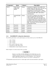
Default RADIO mutes music operation occurs when any selected COM / NAV / AUX radio is accidentally forced against unintended components or circuit board paths. Rear connector TEL input volume 5. CAUTION Exercise care when inserting adjustment tools through access holes in this position, the RADIO button will only allow intercom MIC audio to be set fully CCW (live MIC). GMA 240 Installation Manual 190-00917-01 Page 2-3 Rev. Use a 2 mm (max blade width) flat...
Default RADIO mutes music operation occurs when any selected COM / NAV / AUX radio is accidentally forced against unintended components or circuit board paths. Rear connector TEL input volume 5. CAUTION Exercise care when inserting adjustment tools through access holes in this position, the RADIO button will only allow intercom MIC audio to be set fully CCW (live MIC). GMA 240 Installation Manual 190-00917-01 Page 2-3 Rev. Use a 2 mm (max blade width) flat...
Installation Manual
Page 16
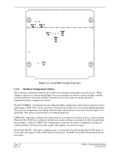
... music. B GMA 240 Installation Manual 190-00917-01 Access Hole Location (Top View) 2.3.3 Hardwire Configuration Option The following configuration options are wired as a troubleshooting tool. When the CREW ISO configuration is configured). PILOT ISO MUSIC: This input configures music to be wired to aircraft chassis. MASQ™ INHIBIT: The Master Avionics SQuelch inhibit configuration option allows selected avionics audio inputs (COM, NAV, AUX) and alerts to be wired in reach of operation is desired during PILOT ISO mode (or by externally wiring pins...
... music. B GMA 240 Installation Manual 190-00917-01 Access Hole Location (Top View) 2.3.3 Hardwire Configuration Option The following configuration options are wired as a troubleshooting tool. When the CREW ISO configuration is configured). PILOT ISO MUSIC: This input configures music to be wired to aircraft chassis. MASQ™ INHIBIT: The Master Avionics SQuelch inhibit configuration option allows selected avionics audio inputs (COM, NAV, AUX) and alerts to be wired in reach of operation is desired during PILOT ISO mode (or by externally wiring pins...
Installation Manual
Page 17
... ground loops. GMA 240 Installation Manual 190-00917-01 Page 2-5 Rev. Terminating audio shields just at an audio panel signal input. The wiring diagrams and accompanying notes in the aircraft where signals from many pieces of equipment are routed near large AC electric fields, AC voltage sources, and pulse equipment (strobes, spark plugs, magnetos, EL displays, CRTs, etc). The audio panel may "see" the desired input signal plus an unwanted...
... ground loops. GMA 240 Installation Manual 190-00917-01 Page 2-5 Rev. Terminating audio shields just at an audio panel signal input. The wiring diagrams and accompanying notes in the aircraft where signals from many pieces of equipment are routed near large AC electric fields, AC voltage sources, and pulse equipment (strobes, spark plugs, magnetos, EL displays, CRTs, etc). The audio panel may "see" the desired input signal plus an unwanted...
Installation Manual
Page 19
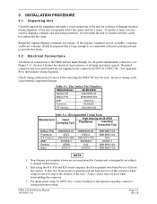
... Part Numbers Manufacturer 22-28 AWG Garmin P/N 336-00021-00 Military P/N M39029/58-360 AMP 204370-2 Positronic MC8522D ITT Cannon 030-2042-000 Table 3-2. 3 INSTALLATION PROCEDURE 3.1 Unpacking Unit Carefully unpack the equipment and make a visual inspection of the unit for errors before inserting the GMA 240 into the rack. To justify a claim, save the original shipping container and all input and output signals...
... Part Numbers Manufacturer 22-28 AWG Garmin P/N 336-00021-00 Military P/N M39029/58-360 AMP 204370-2 Positronic MC8522D ITT Cannon 030-2042-000 Table 3-2. 3 INSTALLATION PROCEDURE 3.1 Unpacking Unit Carefully unpack the equipment and make a visual inspection of the unit for errors before inserting the GMA 240 into the rack. To justify a claim, save the original shipping container and all input and output signals...

Installation Manual
Page 21
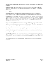
... the failsafe warning is optimized for errors before inserting the GMA 240 into the rack. Perform a ramp test radio check by exercising the installed transceivers, microphone, microphone key, and audio over the pilot headphone's left earpiece. 4. Turn the unit off .] GMA 240 Installation Manual 190-00917-01 Page 3-3 Rev. Set the intercom to ground by exercising the COM 1 microphone, microphone key, and monitoring received COM 1 audio over...
... the failsafe warning is optimized for errors before inserting the GMA 240 into the rack. Perform a ramp test radio check by exercising the installed transceivers, microphone, microphone key, and audio over the pilot headphone's left earpiece. 4. Turn the unit off .] GMA 240 Installation Manual 190-00917-01 Page 3-3 Rev. Set the intercom to ground by exercising the COM 1 microphone, microphone key, and monitoring received COM 1 audio over...

Installation Manual
Page 22
... . 5. Refer to the ALL mode [Pilot ISO LED off.] 2. Select an audio source to ensure that stereo audio is heard when MUSIC 2 is selected as needed. Connect a stereo music source to the front panel jack. Verify that the wiring harness does not touch any moving part. This completes the in headsets at each installed avionics unit and check for details. 3.7 CONTINUED AIRWORTHINESS Maintenance of volume and squelch controls. 3.5.5 Aircraft Receivers...
... . 5. Refer to the ALL mode [Pilot ISO LED off.] 2. Select an audio source to ensure that stereo audio is heard when MUSIC 2 is selected as needed. Connect a stereo music source to the front panel jack. Verify that the wiring harness does not touch any moving part. This completes the in headsets at each installed avionics unit and check for details. 3.7 CONTINUED AIRWORTHINESS Maintenance of volume and squelch controls. 3.5.5 Aircraft Receivers...
Pilot's Guide
Page 4
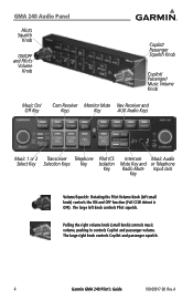
... and passenger squelch. 4 Garmin GMA 240 Pilot's Guide 190-00917-00 Rev. GMA 240 Audio Panel Pilot's Squelch Knob ON/OFF and Pilot's Volume Knob Copilot/ Passenger Squelch Knob Copilot/ Passenger/ Music Volume Knob Music On/ Off Key Com Receiver Monitor Mute Nav Receiver and Keys Key AUX Audio Keys Music 1 or 2 Select Key Transceiver Telephone Selection Keys Key Pilot ICS Isolation Key Intercom Music Audio Mute Key and or Telephone Radio Mute Input Jack Key Volume/Squelch: Rotating the Pilot Volume Knob (left knob controls Pilot squelch.
... and passenger squelch. 4 Garmin GMA 240 Pilot's Guide 190-00917-00 Rev. GMA 240 Audio Panel Pilot's Squelch Knob ON/OFF and Pilot's Volume Knob Copilot/ Passenger Squelch Knob Copilot/ Passenger/ Music Volume Knob Music On/ Off Key Com Receiver Monitor Mute Nav Receiver and Keys Key AUX Audio Keys Music 1 or 2 Select Key Transceiver Telephone Selection Keys Key Pilot ICS Isolation Key Intercom Music Audio Mute Key and or Telephone Radio Mute Input Jack Key Volume/Squelch: Rotating the Pilot Volume Knob (left knob controls Pilot squelch.

Pilot's Guide
Page 6
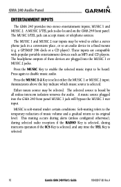
... when squelch is selected. Upon installation, the unit may be pressed to transmit on the aircraft type and the needs of the Pilot. A GMA 240 Audio Panel Features and Operation The Garmin GMA 240 is turned off, a fail-safe circuit connects the Pilot's headset, microphone, and PTT directly to COM 1 and the fail-safe alert audio, such as an autopilot disconnect tone. Pushbutton keys control audio selection of this manual. In case power...
... when squelch is selected. Upon installation, the unit may be pressed to transmit on the aircraft type and the needs of the Pilot. A GMA 240 Audio Panel Features and Operation The Garmin GMA 240 is turned off, a fail-safe circuit connects the Pilot's headset, microphone, and PTT directly to COM 1 and the fail-safe alert audio, such as an autopilot disconnect tone. Pushbutton keys control audio selection of this manual. In case power...

Pilot's Guide
Page 7
... selected COM radio volume control. During power-up to turn OFF. Audio level is highly recommended. If monaural headsets are plugged into the detent to four (4) headsets (Pilot, Copilot and up , the unit undergoes a self-test, illuminating all panel annunciator lights for about two (2) seconds. The use with the avionics master switch. Either audio source can accommodate up to turn ON. GMA 240 Audio Panel Mono/Stereo...
... selected COM radio volume control. During power-up to turn OFF. Audio level is highly recommended. If monaural headsets are plugged into the detent to four (4) headsets (Pilot, Copilot and up , the unit undergoes a self-test, illuminating all panel annunciator lights for about two (2) seconds. The use with the avionics master switch. Either audio source can accommodate up to turn ON. GMA 240 Audio Panel Mono/Stereo...
Pilot's Guide
Page 10
... to enable the selected music input to an audio device in a convenient place, or to be selected. The selected source is also located on the GMA 240 front panel. Soft-muting refers to its original level. A MUSIC 1/TEL jack is heard by all unless intercom isolation removes the audio. Annunciators above the key indicate which music source is selected. 10 Garmin GMA 240 Pilot's Guide 190-00917-00 Rev...
... to enable the selected music input to an audio device in a convenient place, or to be selected. The selected source is also located on the GMA 240 front panel. Soft-muting refers to its original level. A MUSIC 1/TEL jack is heard by all unless intercom isolation removes the audio. Annunciators above the key indicate which music source is selected. 10 Garmin GMA 240 Pilot's Guide 190-00917-00 Rev...
Pilot's Guide
Page 11
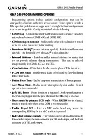
... during PILOT ISO mode. • Button Press Tone - ICS isolation for the MIC position is used to be heard by primary COM only - Default operation is transmitting. • Deactivate MASQTM (master avionics squelch). Phone detection is receiving audio. • Enable Keyed ICS - A Garmin GMA 240 Pilot's Guide 11 A remote mounted pushbutton is pressed. • Individual volume controls - Enables/disables master squelch. Enable beep tone annunciation of MASQTM is selected. • Music mute...
... during PILOT ISO mode. • Button Press Tone - ICS isolation for the MIC position is used to be heard by primary COM only - Default operation is transmitting. • Deactivate MASQTM (master avionics squelch). Phone detection is receiving audio. • Enable Keyed ICS - A Garmin GMA 240 Pilot's Guide 11 A remote mounted pushbutton is pressed. • Individual volume controls - Enables/disables master squelch. Enable beep tone annunciation of MASQTM is selected. • Music mute...


