
?Important Safety and Product Information
Page 2
... safety, always resolve any Garmin warranty service station. Failure to heed this distributor provides local service for your device. Battery Warnings The device uses an internal, non-user-replaceable battery for warranty verification. FCC Compliance This device complies with guarantees that the structure, organization, and code of your vessel. This equipment generates, uses, and can radiate radio frequency energy and may...
... safety, always resolve any Garmin warranty service station. Failure to heed this distributor provides local service for your device. Battery Warnings The device uses an internal, non-user-replaceable battery for warranty verification. FCC Compliance This device complies with guarantees that the structure, organization, and code of your vessel. This equipment generates, uses, and can radiate radio frequency energy and may...
Owner s Manual
Page 3
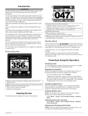
... screen. Introduction WARNING See the Important Safety and Product Information guide in the product box for product warnings and other boats. You can engage the autopilot heading hold functionality, the system allows manual steering and several modes of the helm and steers the boat to maintain your boat. Powerboat Autopilot Operation Heading Hold You can operate the autopilot system using the helm...
... screen. Introduction WARNING See the Important Safety and Product Information guide in the product box for product warnings and other boats. You can engage the autopilot heading hold functionality, the system allows manual steering and several modes of the helm and steers the boat to maintain your boat. Powerboat Autopilot Operation Heading Hold You can operate the autopilot system using the helm...
Installation Instructions
Page 1
... boat. Contacting Garmin Product Support • Go to www.garmin.com/support and click Contact Support for the safe and prudent operation of your GHP 20 system in the product box for use with a fire enclosure. Professional installation of fuel tanks, electrical cables, and hydraulic hoses. Read all installation instructions before proceeding with your boat, install the Garmin® GHP 20 marine autopilot system according to the following instructions. The serial...
... boat. Contacting Garmin Product Support • Go to www.garmin.com/support and click Contact Support for the safe and prudent operation of your GHP 20 system in the product box for use with a fire enclosure. Professional installation of fuel tanks, electrical cables, and hydraulic hoses. Read all installation instructions before proceeding with your boat, install the Garmin® GHP 20 marine autopilot system according to the following instructions. The serial...
Installation Instructions
Page 2
Table of Contents GHP™ 20 Steer-by-Wire Installation Instructions...........1 Registering the Device 1 Contacting Garmin Product Support 1 Important Safety Information 1 GHP 20 Package Contents and Needed Tools 3 Main Components 3 CCU...3 GHC 20 3 Cables and Connectors 3 Steering Controller Cable 3 Alarm 3 GHC 20 NMEA 0183 Data Cable 3 NMEA 2000 Cables and Connectors 3 Tools Needed 4 Installation Preparation 5 Mounting and Connection Considerations 5 CCU Mounting Considerations 5 CCU Connection Considerations 5 Alarm Mounting Considerations 5 Alarm Connection...
Table of Contents GHP™ 20 Steer-by-Wire Installation Instructions...........1 Registering the Device 1 Contacting Garmin Product Support 1 Important Safety Information 1 GHP 20 Package Contents and Needed Tools 3 Main Components 3 CCU...3 GHC 20 3 Cables and Connectors 3 Steering Controller Cable 3 Alarm 3 GHC 20 NMEA 0183 Data Cable 3 NMEA 2000 Cables and Connectors 3 Tools Needed 4 Installation Preparation 5 Mounting and Connection Considerations 5 CCU Mounting Considerations 5 CCU Connection Considerations 5 Alarm Mounting Considerations 5 Alarm Connection...

Installation Instructions
Page 3
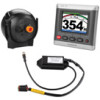
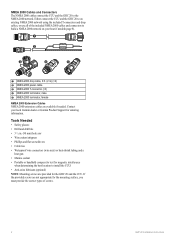
... Number GHP 20 Installation Instructions 3 Familiarize yourself with the GHP 20 components, confirm that the steering controller CAN bus is the primary interface used to communicate with the GHC 20, and to determine heading. If any parts are not available, you can be used to optional NMEA 2000-compatible GPS devices (page 8). CCU Cables and Connectors The GHP 20 autopilot system includes multiple cables. This cable connects the...
... Number GHP 20 Installation Instructions 3 Familiarize yourself with the GHP 20 components, confirm that the steering controller CAN bus is the primary interface used to communicate with the GHC 20, and to determine heading. If any parts are not available, you can be used to optional NMEA 2000-compatible GPS devices (page 8). CCU Cables and Connectors The GHP 20 autopilot system includes multiple cables. This cable connects the...
Installation Instructions
Page 4
... flat screwdrivers • Cable ties • Waterproof wire connectors (wire nuts) or heat-shrink tubing and a heat gun • Marine sealant • Portable or handheld compass (to test for magnetic interference when determining the best location to an existing NMEA 2000 network using the included T-connectors and drop cables, or use all of screws. 4 GHP 20 Installation Instructions If the provided...
... flat screwdrivers • Cable ties • Waterproof wire connectors (wire nuts) or heat-shrink tubing and a heat gun • Marine sealant • Portable or handheld compass (to test for magnetic interference when determining the best location to an existing NMEA 2000 network using the included T-connectors and drop cables, or use all of screws. 4 GHP 20 Installation Instructions If the provided...
Installation Instructions
Page 5
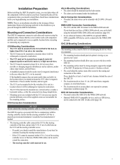
... network. Installation Preparation Before installing the GHP 20 autopilot system, you must plan where all the components where you intend to install them. Remove the last page and refer to test for the mounting surface. CCU Mounting Considerations • The CCU must be mounted in the forward half of the GHP 20, an optional NMEA 2000-compatible GPS device can be used to the...
... network. Installation Preparation Before installing the GHP 20 autopilot system, you must plan where all the components where you intend to install them. Remove the last page and refer to test for the mounting surface. CCU Mounting Considerations • The CCU must be mounted in the forward half of the GHP 20, an optional NMEA 2000-compatible GPS device can be used to the...

Installation Instructions
Page 6
... power cable must be installed only if you are building a NMEA 2000 network. Follow the detailed installation instructions for more information. ➐ Alarm Wire the steering controller cable to the NMEA 2000 network using the supplied cables and connectors (page 10). ➌ NMEA 2000 power cable This cable should be connected to the alarm (page 7). 6 GHP 20 Installation Instructions See the steering controller documentation or www.garmin...
... power cable must be installed only if you are building a NMEA 2000 network. Follow the detailed installation instructions for more information. ➐ Alarm Wire the steering controller cable to the NMEA 2000 network using the supplied cables and connectors (page 10). ➌ NMEA 2000 power cable This cable should be connected to the alarm (page 7). 6 GHP 20 Installation Instructions See the steering controller documentation or www.garmin...

Installation Instructions
Page 7
... alarm (page 7). The steering controller cable allows the GHP 20 Autopilot System to accurately read your boat for your boat. 2. Installing the CCU Mounting Bracket Before you can mount the alarm, you must mount it to your boat (page 7), connect it to the alarm (page 7). Place the CCU in the mounting portion of the bracket with the wires hanging straight down , connect the...
... alarm (page 7). The steering controller cable allows the GHP 20 Autopilot System to accurately read your boat for your boat. 2. Installing the CCU Mounting Bracket Before you can mount the alarm, you must mount it to your boat (page 7), connect it to the alarm (page 7). Place the CCU in the mounting portion of the bracket with the wires hanging straight down , connect the...
Installation Instructions
Page 8
..., use advanced features of the GHP 20, optional NMEA 2000-compatible or NMEA 0183-compatible GPS devices, can install multiple GHC 20 devices (sold separately) to control the autopilot from the adhesive on your boat, all the parts needed to build one power source should already be connected to the CCU through NMEA 0183. 13. Before you can mount the...
..., use advanced features of the GHP 20, optional NMEA 2000-compatible or NMEA 0183-compatible GPS devices, can install multiple GHC 20 devices (sold separately) to control the autopilot from the adhesive on your boat, all the parts needed to build one power source should already be connected to the CCU through NMEA 0183. 13. Before you can mount the...

Installation Instructions
Page 9
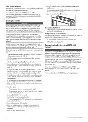
...disconnected T‑connector or backbone extension cable. 5. If the included drop cable is not long enough, you can use a drop cable up to the T-connector. Connect the drop cable to the to an Existing NMEA 2000 Network 1. If the included drop cable is not long enough, you ...4, and connect it to 20 ft. (6 m) long (not included). 6. Route the included drop cable ➍ to the bottom of the T-connector added in step 3, and to the side of a NMEA 2000 T-connector from the network. 3. GHP 20 Installation Instructions 9 Connecting the CCU to the GHC 20. 7. Add the included T&#...
...disconnected T‑connector or backbone extension cable. 5. If the included drop cable is not long enough, you can use a drop cable up to the T-connector. Connect the drop cable to the to an Existing NMEA 2000 Network 1. If the included drop cable is not long enough, you ...4, and connect it to 20 ft. (6 m) long (not included). 6. Route the included drop cable ➍ to the bottom of the T-connector added in step 3, and to the side of a NMEA 2000 T-connector from the network. 3. GHP 20 Installation Instructions 9 Connecting the CCU to the GHC 20. 7. Add the included T&#...

Installation Instructions
Page 10
..., use advanced features of the T-connectors. 4. Determine the NMEA 0183 connection assignments of the boat if possible, or through a switch. Connect your battery if the NMEA 2000 power cable is not necessary for extended runs of various connection situations are provided in the appendix (page 14). 3. Solder and cover all bare-wire connections. 10 GHP 20 Installation Instructions Connect...
..., use advanced features of the T-connectors. 4. Determine the NMEA 0183 connection assignments of the boat if possible, or through a switch. Connect your battery if the NMEA 2000 power cable is not necessary for extended runs of various connection situations are provided in the appendix (page 14). 3. Solder and cover all bare-wire connections. 10 GHP 20 Installation Instructions Connect...
Installation Instructions
Page 11
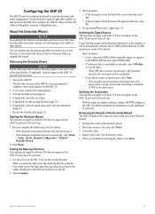
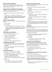
.... If necessary, complete the setup sequence. 3. If applicable, test the steering direction (page 11). 6. Use the arrows on the GHC 20 to configure the GHP 20. Verifying the Tachometer This step may not apply to all boats. If it does not appear on the GHC 20, proceed to the next step. 1. GHP 20 Installation Instructions 11 If one of the...
.... If necessary, complete the setup sequence. 3. If applicable, test the steering direction (page 11). 6. Use the arrows on the GHC 20 to configure the GHP 20. Verifying the Tachometer This step may not apply to all boats. If it does not appear on the GHC 20, proceed to the next step. 1. GHP 20 Installation Instructions 11 If one of the...
Installation Instructions
Page 12
...Setup > Dealer Autopilot Configuration > Wizards > Sea Trial Wizard. 3. Set north (page 12). 7. Calibrating the Compass 1. The GHC 20 displays a completion message when the calibration is in the Sea Trial Wizard. If the autotune procedure continues to fail after you must have a GPS device installed on your boat is normal. 12 GHP 20 Installation Instructions...Sea Trial Wizard configures the fundamental sensors on the autopilot, and it matches north on the GHC 20, use the arrows to adjust the value. 3. When instructed, turn the boat slowly clockwise, taking care to drive in...
...Setup > Dealer Autopilot Configuration > Wizards > Sea Trial Wizard. 3. Set north (page 12). 7. Calibrating the Compass 1. The GHC 20 displays a completion message when the calibration is in the Sea Trial Wizard. If the autotune procedure continues to fail after you must have a GPS device installed on your boat is normal. 12 GHP 20 Installation Instructions...Sea Trial Wizard configures the fundamental sensors on the autopilot, and it matches north on the GHC 20, use the arrows to adjust the value. 3. When instructed, turn the boat slowly clockwise, taking care to drive in...
Installation Instructions
Page 13
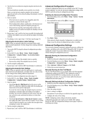
... or High Speed and use the arrows on the Setup screen, the advanced configuration procedure is available on the GHC 20 to counter the original turn smoothly, not too quickly or too slowly. Repeat steps 2 and 3 until the GHP 20 performance is working correctly, you set this value too high, the autopilot may require you manually adjust the acceleration limiter...
... or High Speed and use the arrows on the Setup screen, the advanced configuration procedure is available on the GHC 20 to counter the original turn smoothly, not too quickly or too slowly. Repeat steps 2 and 3 until the GHP 20 performance is working correctly, you set this value too high, the autopilot may require you manually adjust the acceleration limiter...

Installation Instructions
Page 14
...20 ➋ NMEA 2000 network (provides power to the brown wire (Rx/A) from the GHC 20, and connect the green wire (Rx/B) from the GHC 20 unconnected. ➋ ➌ + - ➊ ➊ ➋ > ➌ ➍ > ➍ ➎ > > ➏ Wire GHC 20 Wire Color - Appendix NMEA 0183 Connection Diagrams The following three connection diagrams... lines, it to the GHC 20) ➌ 12 VDC power source ➍ NMEA 0183-compatible device 14 GHP 20 Installation Instructions Example One of Three: Only One Transmitting Wire If your NMEA 0183-compatible device...
...20 ➋ NMEA 2000 network (provides power to the brown wire (Rx/A) from the GHC 20, and connect the green wire (Rx/B) from the GHC 20 unconnected. ➋ ➌ + - ➊ ➊ ➋ > ➌ ➍ > ➍ ➎ > > ➏ Wire GHC 20 Wire Color - Appendix NMEA 0183 Connection Diagrams The following three connection diagrams... lines, it to the GHC 20) ➌ 12 VDC power source ➍ NMEA 0183-compatible device 14 GHP 20 Installation Instructions Example One of Three: Only One Transmitting Wire If your NMEA 0183-compatible device...

Installation Instructions
Page 15
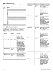
...ISO Request ISO Address Claim NMEA - Rapid Update 129026 COG & SOG - Rapid Update COG & SOG - Rapid Update Cross Track Error Navigation Data GNSS Sats in . Specifications Device CCU Specification Measurement Dimensions 3 /19 32 in View Wind Data GHP 20 Installation Instructions 15 diameter (91.4 mm) Weight 5.6 oz...176;C to 55°C) range GHC 20 Cable length Dimensions Weight Cables 10 ft. (3.0 m) 4 /21 64 × 4 /17 32 × 1 3/16 in. (110 × 115 × 30 mm) 8.71 oz. (247 g) NMEA 0183 data cable - 6 ft. (1.8 m) NMEA 2000 drop cable and power cable - 6 1/2 ft. (2 m) ...
...ISO Request ISO Address Claim NMEA - Rapid Update 129026 COG & SOG - Rapid Update COG & SOG - Rapid Update Cross Track Error Navigation Data GNSS Sats in . Specifications Device CCU Specification Measurement Dimensions 3 /19 32 in View Wind Data GHP 20 Installation Instructions 15 diameter (91.4 mm) Weight 5.6 oz...176;C to 55°C) range GHC 20 Cable length Dimensions Weight Cables 10 ft. (3.0 m) 4 /21 64 × 4 /17 32 × 1 3/16 in. (110 × 115 × 30 mm) 8.71 oz. (247 g) NMEA 0183 data cable - 6 ft. (1.8 m) NMEA 2000 drop cable and power cable - 6 1/2 ft. (2 m) ...
Installation Instructions
Page 16
... NMEA 0183-compatible devices, the GHC 20 uses the following NMEA 0183 sentences. Allows you set the rudder gain for high speeds. If you to correct the steering direction. 16 GHP 20 Installation Instructions You can manually adjust any setting (page 13). Category Rudder Gains Rudder Gains Rudder Gains Rudder Gains NMEA Setup NMEA Setup Setting Low Speed Gain Low Speed Counter...
... NMEA 0183-compatible devices, the GHC 20 uses the following NMEA 0183 sentences. Allows you set the rudder gain for high speeds. If you to correct the steering direction. 16 GHP 20 Installation Instructions You can manually adjust any setting (page 13). Category Rudder Gains Rudder Gains Rudder Gains Rudder Gains NMEA Setup NMEA Setup Setting Low Speed Gain Low Speed Counter...
Installation Instructions
Page 17
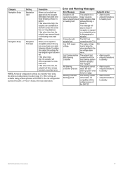
... GHC 20 Owner's Manual for crosstrack error. Low GHC supply voltage The supply voltage N/A level is too high, the autopilot can oscillate back and forth across the course line over long distances. If this setting after the navigation gain has been set. Lost Communication The autopilot lost N/A connection with the • Autopilot transitions Controller boat steering system to engage. GHP 20 Installation Instructions 17...
... GHC 20 Owner's Manual for crosstrack error. Low GHC supply voltage The supply voltage N/A level is too high, the autopilot can oscillate back and forth across the course line over long distances. If this setting after the navigation gain has been set. Lost Communication The autopilot lost N/A connection with the • Autopilot transitions Controller boat steering system to engage. GHP 20 Installation Instructions 17...

Installation Instructions
Page 19
... 0183-compatible GPS device to understand the necessary electrical and data connections. 2. Contact Garmin Product Support if you have any questions during the installation process. 1. Connect the CCU to the steering system of magnetic interference. GHP 20 Installation Checklist Detach this checklist from the installation instructions and use it to a NMEA 2000 network. Configure the GHP 20 system (page 11). Check the cable lengths. Use a handheld...
... 0183-compatible GPS device to understand the necessary electrical and data connections. 2. Contact Garmin Product Support if you have any questions during the installation process. 1. Connect the CCU to the steering system of magnetic interference. GHP 20 Installation Checklist Detach this checklist from the installation instructions and use it to a NMEA 2000 network. Configure the GHP 20 system (page 11). Check the cable lengths. Use a handheld...


