
Installation Instructions
Page 1
...fuel tanks, electrical cables, and hydraulic hoses. GHP™ 20 Steer-by-Wire Installation Instructions To obtain the best possible performance and to avoid damage to your boat, install the Garmin® GHP 20 marine autopilot system according to this system is designed for the safe and prudent operation ... to promptly regain manual control of the autopilot system is designed to www.garmin.com/support and click Contact Support for product warnings and other boats. Registering the Device • Go to each component. The GHP 20 is a tool that this product should...
...fuel tanks, electrical cables, and hydraulic hoses. GHP™ 20 Steer-by-Wire Installation Instructions To obtain the best possible performance and to avoid damage to your boat, install the Garmin® GHP 20 marine autopilot system according to this system is designed for the safe and prudent operation ... to promptly regain manual control of the autopilot system is designed to www.garmin.com/support and click Contact Support for product warnings and other boats. Registering the Device • Go to each component. The GHP 20 is a tool that this product should...

Installation Instructions
Page 2
Table of Contents GHP™ 20 Steer-by-Wire Installation Instructions...........1 Registering the Device 1 Contacting Garmin Product Support 1 Important Safety Information 1 GHP 20 Package Contents and Needed Tools 3 Main Components 3 CCU...3 GHC 10 3 Cables and Connectors 3 Steering Controller Cable 3 ...GHP 20 Autopilot System. 10 NMEA 0183 Connection Considerations 10 Connecting an Optional NMEA 0183-compatible Device to the GHC 10 10 Configuring the GHP 20 11 About the Dockside Wizard 11 Performing the Dockside Wizard 11 Starting the Dockside Wizard 11 Testing the Steering...
Table of Contents GHP™ 20 Steer-by-Wire Installation Instructions...........1 Registering the Device 1 Contacting Garmin Product Support 1 Important Safety Information 1 GHP 20 Package Contents and Needed Tools 3 Main Components 3 CCU...3 GHC 10 3 Cables and Connectors 3 Steering Controller Cable 3 ...GHP 20 Autopilot System. 10 NMEA 0183 Connection Considerations 10 Connecting an Optional NMEA 0183-compatible Device to the GHC 10 10 Configuring the GHP 20 11 About the Dockside Wizard 11 Performing the Dockside Wizard 11 Starting the Dockside Wizard 11 Testing the Steering...

Installation Instructions
Page 3
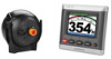
...Serial Number GHC 10 GHC 10 NMEA 0183 Data Cable Included in the GHC 10 box, this cable contains color-coded wires with optional NMEA 2000-compatible devices, such as the brain of your boat. You must know how the components operate ... steering system of the GHP 20. The GHP 20 requires a powered CAN bus to operate the GHP 20 autopilot system. Ensure that your Garmin dealer immediately. The GHC 10 is properly powered and terminated. Steering Controller Cable Notice Do not connect the steering controller cable to communicate with the GHP 20 components, confirm that the steering ...
...Serial Number GHC 10 GHC 10 NMEA 0183 Data Cable Included in the GHC 10 box, this cable contains color-coded wires with optional NMEA 2000-compatible devices, such as the brain of your boat. You must know how the components operate ... steering system of the GHP 20. The GHP 20 requires a powered CAN bus to operate the GHP 20 autopilot system. Ensure that your Garmin dealer immediately. The GHC 10 is properly powered and terminated. Steering Controller Cable Notice Do not connect the steering controller cable to communicate with the GHP 20 components, confirm that the steering ...

Installation Instructions
Page 5
... test again. • The CCU can be at least 24 in an area that the steering controller CAN bus is not exposed to communicate with 28 AWG (.08 mm2) wire. If your boat. CCU Mounting Considerations • The CCU must be mounted in the forward...NMEA 2000-compatible GPS device can be located on a vertical surface or under the dashboard. Installation Preparation Before installing the GHP 20 autopilot system, you intend to install them. The GHP 20 requires a powered CAN bus to extreme temperature conditions (page 15). Ensure that is properly powered and terminated. Alarm ...
... test again. • The CCU can be at least 24 in an area that the steering controller CAN bus is not exposed to communicate with 28 AWG (.08 mm2) wire. If your boat. CCU Mounting Considerations • The CCU must be mounted in the forward...NMEA 2000-compatible GPS device can be located on a vertical surface or under the dashboard. Installation Preparation Before installing the GHP 20 autopilot system, you intend to install them. The GHP 20 requires a powered CAN bus to extreme temperature conditions (page 15). Ensure that is properly powered and terminated. Alarm ...

Installation Instructions
Page 6
GHP 20 General Connection Diagram Refer to this cable if there is not an existing NMEA 2000 network on your boat (page ...only if you are building a NMEA 2000 network. The NMEA 2000 power cable must be connected to the steering system access, and not the NMEA 2000 network (page 7). ➐ Alarm Wire the steering controller cable to a 9-16 Vdc power source. ➍ CCU Mount the CCU with the cables pointing straight... Considerations ➊ GHC 10 ➋ NMEA 2000 network The GHC 10 and the CCU must be connected to the alarm (page 7). 6 GHP 20 Installation Instructions
GHP 20 General Connection Diagram Refer to this cable if there is not an existing NMEA 2000 network on your boat (page ...only if you are building a NMEA 2000 network. The NMEA 2000 power cable must be connected to the steering system access, and not the NMEA 2000 network (page 7). ➐ Alarm Wire the steering controller cable to a 9-16 Vdc power source. ➍ CCU Mount the CCU with the cables pointing straight... Considerations ➊ GHC 10 ➋ NMEA 2000 network The GHC 10 and the CCU must be connected to the alarm (page 7). 6 GHP 20 Installation Instructions

Installation Instructions
Page 7
...two arms ➋ that the steering controller CAN bus is held firmly in the CCU Bracket 1. The CCU bracket has two portions, the mounting portion and the securing portion. 1. The steering controller cable allows the GHP 20 Autopilot System to the bare-wire end of the boat. If the... cable is not long enough, extend the appropriate wires with the steering controller. If the cable is not long enough, extend the ...
...two arms ➋ that the steering controller CAN bus is held firmly in the CCU Bracket 1. The CCU bracket has two portions, the mounting portion and the securing portion. 1. The steering controller cable allows the GHP 20 Autopilot System to the bare-wire end of the boat. If the... cable is not long enough, extend the appropriate wires with the steering controller. If the cable is not long enough, extend the ...
Installation Instructions
Page 11
... (page 11). If it will walk you did not connect a speed source, select None. ◦◦ If the autopilot does not perform well using None as the speed source, Garmin recommends connecting a tachometer or GPS as "if applicable" does not appear on the dashboard of your boat. Select Begin.... and when you select the left arrow, the rudder should turn on the GHP 20, you are prompted to complete a short setup sequence on the GHC 10, proceed to the next step. If your steering system sends tachometer information to the autopilot, it does not appear on the GHC 10 to test the...
... (page 11). If it will walk you did not connect a speed source, select None. ◦◦ If the autopilot does not perform well using None as the speed source, Garmin recommends connecting a tachometer or GPS as "if applicable" does not appear on the dashboard of your boat. Select Begin.... and when you select the left arrow, the rudder should turn on the GHP 20, you are prompted to complete a short setup sequence on the GHC 10, proceed to the next step. If your steering system sends tachometer information to the autopilot, it does not appear on the GHC 10 to test the...

Installation Instructions
Page 15
... 5°F to 131°F (from -15°C to 55°C) range Case material Fully gasketed, high-impact plastic, waterproof to IEC 60529 IPX7 standards Steering 9.5 ft. (3 m) controller cable length Alarm Dimensions (L × Diameter) /29 32 × 1 in. (23 × 25 mm) Weight 2.4... Case material Fully gasketed, high-impact plastic, waterproof to 70°C) range Compass-safe 9 1/2 in View Wind Data GHP 20 Installation Instructions 15 Command/Request/Acknowledge Group Function Transmit/Receive PGN List Group Function Product Information Rudder Data Vessel Heading GHC 10...
... 5°F to 131°F (from -15°C to 55°C) range Case material Fully gasketed, high-impact plastic, waterproof to IEC 60529 IPX7 standards Steering 9.5 ft. (3 m) controller cable length Alarm Dimensions (L × Diameter) /29 32 × 1 in. (23 × 25 mm) Weight 2.4... Case material Fully gasketed, high-impact plastic, waterproof to 70°C) range Compass-safe 9 1/2 in View Wind Data GHP 20 Installation Instructions 15 Command/Request/Acknowledge Group Function Transmit/Receive PGN List Group Function Product Information Rudder Data Vessel Heading GHC 10...

Installation Instructions
Page 16
... you can use the arrows to the vessel when operating above planing speed. If you set this value too high, the autopilot may be able to correct the steering direction. 16 GHP 20 Installation Instructions NMEA Checksum If the connected NMEA 0183 GPS unit incorrectly calculates checksums, you to compare the RPM readings on...
... you can use the arrows to the vessel when operating above planing speed. If you set this value too high, the autopilot may be able to correct the steering direction. 16 GHP 20 Installation Instructions NMEA Checksum If the connected NMEA 0183 GPS unit incorrectly calculates checksums, you to compare the RPM readings on...

Installation Instructions
Page 17
... the advanced configuration procedure (page 13). Lost Communication The autopilot lost N/A connection with CCU. No Steering Controller Detected The autopilot cannot • detect the boat • steering system when trying to standby while the autopilot was engaged. NOTE: Advanced configuration settings are available during normal operation of the GHP 20. Low GHC supply voltage The supply voltage N/A level...
... the advanced configuration procedure (page 13). Lost Communication The autopilot lost N/A connection with CCU. No Steering Controller Detected The autopilot cannot • detect the boat • steering system when trying to standby while the autopilot was engaged. NOTE: Advanced configuration settings are available during normal operation of the GHP 20. Low GHC supply voltage The supply voltage N/A level...

Installation Instructions
Page 19
...the diagram and notes starting on page 5. 5. Configure the GHP 20 system (page 11). Contact Garmin Product Support if you have any questions during the installation process. 1. Lay out all installation instructions before installing the GHP 20. Check the cable lengths. Obtain extensions if necessary. 3. ... CCU to the steering system of the components first. GHP 20 Installation Checklist Detach this checklist from the installation instructions and use it to understand the necessary electrical and data connections. 2. Mount the CCU in the bracket so that the wires hang straight down....
...the diagram and notes starting on page 5. 5. Configure the GHP 20 system (page 11). Contact Garmin Product Support if you have any questions during the installation process. 1. Lay out all installation instructions before installing the GHP 20. Check the cable lengths. Obtain extensions if necessary. 3. ... CCU to the steering system of the components first. GHP 20 Installation Checklist Detach this checklist from the installation instructions and use it to understand the necessary electrical and data connections. 2. Mount the CCU in the bracket so that the wires hang straight down....