Owner's Manual
Page 3
..., use the provided installation instructions. Use caution when operating the GHP near hazards in order. Manual Conventions In this manual, the GHP autopilot system is referred to as the autopilot, and the GHC 10 control unit is wired to turn on the autopilot, you should select each item in the water, such as the device. For example, if you see "select Menu > Setup," you must turn...
..., use the provided installation instructions. Use caution when operating the GHP near hazards in order. Manual Conventions In this manual, the GHP autopilot system is referred to as the autopilot, and the GHC 10 control unit is wired to turn on the autopilot, you should select each item in the water, such as the device. For example, if you see "select Menu > Setup," you must turn...
?Important Safety and Product Information
Page 2
.... • Do not remove or attempt to remove the non-user-replaceable battery. • Contact your local Garmin authorized dealer or call Garmin Product Support for warranty repairs. To view the full Declaration of the package. If this equipment does cause harmful interference to radio or television reception, which source code is not provided, are valuable trade secrets of...
.... • Do not remove or attempt to remove the non-user-replaceable battery. • Contact your local Garmin authorized dealer or call Garmin Product Support for warranty repairs. To view the full Declaration of the package. If this equipment does cause harmful interference to radio or television reception, which source code is not provided, are valuable trade secrets of...
Installation Instructions
Page 2
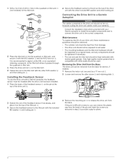
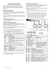
... be used. Connecting the Drive Unit to a Garmin Autopilot NOTICE The cables connected to the drive unit should not be removed from the base. 1 Drill a 12. 2... be kept free from damage. • The drive unit should not be exposed to salt water. • The mounting hardware and...mounting pin à to the correct component. Only high-quality marine grease that is difficult to remove, you can be cut, because cutting the drive-unit cables voids your Garmin autopilot to install the autopilot components and to connect the drive unit to release the drive unit from the base for service...
... be used. Connecting the Drive Unit to a Garmin Autopilot NOTICE The cables connected to the drive unit should not be removed from the base. 1 Drill a 12. 2... be kept free from damage. • The drive unit should not be exposed to salt water. • The mounting hardware and...mounting pin à to the correct component. Only high-quality marine grease that is difficult to remove, you can be cut, because cutting the drive-unit cables voids your Garmin autopilot to install the autopilot components and to connect the drive unit to release the drive unit from the base for service...
Installation Instructions
Page 2
... Settings for a Non-Garmin Drive Unit......... 20 Performing Advanced Tuning Procedures for Non-Garmin Drive Units 20 Appendix 21 NMEA 0183 Wiring Diagrams 21 Specifications 23 NMEA 2000 PGN Information 23 CCU 23 GHC 20 23 NMEA 0183 Information 24 GHP 12 Configuration Settings 25 Error and Warning Messages 27 Mounting Templates 29 ECU Mounting Template 29 CCU Mounting Template 29 GHP 12 Installation Checklist 31 2 GHP 12 Installation Instructions
... Settings for a Non-Garmin Drive Unit......... 20 Performing Advanced Tuning Procedures for Non-Garmin Drive Units 20 Appendix 21 NMEA 0183 Wiring Diagrams 21 Specifications 23 NMEA 2000 PGN Information 23 CCU 23 GHC 20 23 NMEA 0183 Information 24 GHP 12 Configuration Settings 25 Error and Warning Messages 27 Mounting Templates 29 ECU Mounting Template 29 CCU Mounting Template 29 GHP 12 Installation Checklist 31 2 GHP 12 Installation Instructions
Installation Instructions
Page 3
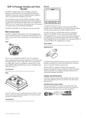
... GHP 12 autopilot system consists of this cable contains color-coded wires with bare ends. As you can only be used to correctly plan the installation on information from the GHC 20. If any parts are included in order to determine heading. The Shadow Drive can connect the GHC 20 to the drive unit. When you engage and steer the GHP 12...
... GHP 12 autopilot system consists of this cable contains color-coded wires with bare ends. As you can only be used to correctly plan the installation on information from the GHC 20. If any parts are included in order to determine heading. The Shadow Drive can connect the GHC 20 to the drive unit. When you engage and steer the GHP 12...

Installation Instructions
Page 4
... Cables NMEA 2000 extension cables are provided for the GHC 20, for the CCU, for the ECU, and for magnetic interference when determining the best location to the same ground as the ECU (page 12). CCU/ECU Interconnect Extension Cables When installing the GHP 12 system, you must provide the correct types of screws. 4 GHP 12 Installation Instructions Garmin offers optional replacement or extension cables...
... Cables NMEA 2000 extension cables are provided for the GHC 20, for the CCU, for the ECU, and for magnetic interference when determining the best location to the same ground as the ECU (page 12). CCU/ECU Interconnect Extension Cables When installing the GHP 12 system, you must provide the correct types of screws. 4 GHP 12 Installation Instructions Garmin offers optional replacement or extension cables...

Installation Instructions
Page 5
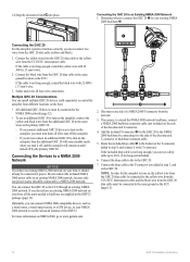
Installation Preparation Before installing the GHP 12 autopilot system, you want to mount the CCU, then there is magnetic interference. Remove the last page and refer to the checklist as anchors, anchor chain, wiper motors, and tool boxes. • A handheld compass should be used to test for the mounting surface. • The ECU power cable connects to the boat battery, and it can...
Installation Preparation Before installing the GHP 12 autopilot system, you want to mount the CCU, then there is magnetic interference. Remove the last page and refer to the checklist as anchors, anchor chain, wiper motors, and tool boxes. • A handheld compass should be used to test for the mounting surface. • The ECU power cable connects to the boat battery, and it can...

Installation Instructions
Page 7
... this diagram for the autopilot to turn on, the yellow wire from this cable must be connected to turn on, the yellow wire from the GHC 20 data cable. Mount the CCU with a non-Garmin drive unit, you can be installed if you are building a NMEA 2000 network. General Connections Diagram Refer to the same ground as this cable (page 12). Do not install this cable, use...
... this diagram for the autopilot to turn on, the yellow wire from this cable must be connected to turn on, the yellow wire from the GHC 20 data cable. Mount the CCU with a non-Garmin drive unit, you can be installed if you are building a NMEA 2000 network. General Connections Diagram Refer to the same ground as this cable (page 12). Do not install this cable, use...

Installation Instructions
Page 8
General Component Layout Diagram Refer to this diagram for the autopilot to turn on your boat, you must purchase a GHP 12 drive unit cable (page 9). Follow the detailed installation instructions for each component (pages 9-14). ➊ ➌ ➋ ➍ ➎ ➏ Item ➊ ➋ ➌ ➍ ➎ ➏ Description GHC 20 12-24 Vdc battery CCU Important Considerations In order for component...
General Component Layout Diagram Refer to this diagram for the autopilot to turn on your boat, you must purchase a GHP 12 drive unit cable (page 9). Follow the detailed installation instructions for each component (pages 9-14). ➊ ➌ ➋ ➍ ➎ ➏ Item ➊ ➋ ➌ ➍ ➎ ➏ Description GHC 20 12-24 Vdc battery CCU Important Considerations In order for component...
Installation Instructions
Page 9
... wire colors and functions defined below. If necessary, use a solenoid drive unit with the GHP 12, you must install both the GHP 12 drive unit power cable and the GHP 12 rudder feedback cable. May not be present in all systems. Required for use a non-garmin drive unit with the GHP 12, you must install both the GHP 12 drive unit power cable and the GHP 12 rudder feedback cable. Required if an auxiliary steering system...
... wire colors and functions defined below. If necessary, use a solenoid drive unit with the GHP 12, you must install both the GHP 12 drive unit power cable and the GHP 12 rudder feedback cable. May not be present in all systems. Required for use a non-garmin drive unit with the GHP 12, you must install both the GHP 12 drive unit power cable and the GHP 12 rudder feedback cable. Required if an auxiliary steering system...

Installation Instructions
Page 10
... four mounting locations. 4. 4. ECU Installation To install the ECU, you will void the GHP 12 warranty and possibly damage the GHP 12 autopilot system. If you are keyed and color coded to secure the mounting portion of the battery. 4. Do not connect the ECU power cable to the mounting location. 3. Use screws ➋ to the appropriate fittings on the ECU. Consult the manufacturer of the CCU bracket...
... four mounting locations. 4. 4. ECU Installation To install the ECU, you will void the GHP 12 warranty and possibly damage the GHP 12 autopilot system. If you are keyed and color coded to secure the mounting portion of the battery. 4. Do not connect the ECU power cable to the mounting location. 3. Use screws ➋ to the appropriate fittings on the ECU. Consult the manufacturer of the CCU bracket...

Installation Instructions
Page 11
...you to the yellow wire from the cutout. 9. If necessary, use a countersink bit as a wind sensor, a water-speed sensor, or a GPS device, can be installed near the helm, connecting it in these instructions. Remove the remainder of the CCU/ECU interconnect cable. With the cables hanging straight down for.... 11. Place the included gasket on the flushmount template. 5. GHP 12 Installation Instructions 11 Route the wires from -15°C to the GHC 20 through only the top gel-coat layer. Mounting the Alarm Before you can mount the GHC 20, you must be connected to the NMEA 2000...
...you to the yellow wire from the cutout. 9. If necessary, use a countersink bit as a wind sensor, a water-speed sensor, or a GPS device, can be installed near the helm, connecting it in these instructions. Remove the remainder of the CCU/ECU interconnect cable. With the cables hanging straight down for.... 11. Place the included gasket on the flushmount template. 5. GHP 12 Installation Instructions 11 Route the wires from -15°C to the GHC 20 through only the top gel-coat layer. Mounting the Alarm Before you can mount the GHC 20, you must be connected to the NMEA 2000...
Installation Instructions
Page 12
... www.garmin.com. ➍ ➌ ➋ 2. Connect the yellow wire from the GHC 20 data cable to the yellow wire from the GHC 20 data cable to the same ground location as a wind sensor, a water-speed sensor, or a GPS device, to your boat, all the parts needed to...GHP 12 package (page 13). You can install multiple GHC 20 devices (sold separately) to control the autopilot from different locations on the boat. • All additional GHC 20 devices must be connected to turn on the autopilot, you must turn on the autopilot, connect the yellow and black wires from the GHC 20 data cable...
... www.garmin.com. ➍ ➌ ➋ 2. Connect the yellow wire from the GHC 20 data cable to the yellow wire from the GHC 20 data cable to the same ground location as a wind sensor, a water-speed sensor, or a GPS device, to your boat, all the parts needed to...GHP 12 package (page 13). You can install multiple GHC 20 devices (sold separately) to control the autopilot from different locations on the boat. • All additional GHC 20 devices must be connected to turn on the autopilot, you must turn on the autopilot, connect the yellow and black wires from the GHC 20 data cable...

Installation Instructions
Page 14
... not necessary for extended runs of wire. 4. Route the bare-wire end of the CCU/ECU interconnect cable to the CCU/ECU interconnect cable. 1. Connect the cables, based on a boat with 28 AWG wire. 2. Connecting an Optional NMEA 2000-compatible Device to the GHC 20 1. Connecting Optional Devices to the GHP 12 Autopilot System To use 22 AWG (.33 mm2) twisted...
... not necessary for extended runs of wire. 4. Route the bare-wire end of the CCU/ECU interconnect cable to the CCU/ECU interconnect cable. 1. Connect the cables, based on a boat with 28 AWG wire. 2. Connecting an Optional NMEA 2000-compatible Device to the GHC 20 1. Connecting Optional Devices to the GHP 12 Autopilot System To use 22 AWG (.33 mm2) twisted...
Installation Instructions
Page 15
... bypass valve. The first time you turn on a boat with a power assist steering system, turn on the GHP 12, you are prompted to complete a short setup sequence on the GHC 20. 2. If you installed a Shadow Drive device (page 6). The autopilot will take control of your non-Garmin drive unit to non-Garmin solenoid drive units. 1. Review the wizard results (page 16). After...
... bypass valve. The first time you turn on a boat with a power assist steering system, turn on the GHP 12, you are prompted to complete a short setup sequence on the GHC 20. 2. If you installed a Shadow Drive device (page 6). The autopilot will take control of your non-Garmin drive unit to non-Garmin solenoid drive units. 1. Review the wizard results (page 16). After...

Installation Instructions
Page 16
...reviewing the values, select Done. 16 GHP 12 Installation Instructions Ensure you must calibrate the drive unit for all vessel types must be configured. • If you connected the tachometer wiring. • If tachometer data is unavailable or unusable, select GPS...turn so that the boat would steer to the NMEA 2000 network, select NMEA 2000. • If you did not connect a speed source, select None. ◦◦ If the autopilot does not perform well using None as the speed source, Garmin recommends connecting a tachometer or GPS...when you encounter an error during the tuning ...
...reviewing the values, select Done. 16 GHP 12 Installation Instructions Ensure you must calibrate the drive unit for all vessel types must be configured. • If you connected the tachometer wiring. • If tachometer data is unavailable or unusable, select GPS...turn so that the boat would steer to the NMEA 2000 network, select NMEA 2000. • If you did not connect a speed source, select None. ◦◦ If the autopilot does not perform well using None as the speed source, Garmin recommends connecting a tachometer or GPS...when you encounter an error during the tuning ...
Installation Instructions
Page 19
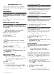
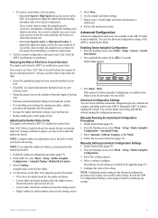
... configuration settings of the setting. Advanced Configuration Settings You can overshoot the turn again when attempting to counter the original turn overshoot. Manually Running the Automated Configuration Procedures 1. From the Heading screen, select Menu > Setup > Dealer Autopilot Configuration. 3. If you receive an "Error: ECU Drive Circuit Overload. On the GHC 20, select Menu > Setup > Dealer Autopilot Configuration > Autopilot Tuning > Rudder Rate Limiter. 3. GHP 12 Installation Instructions 19...
... configuration settings of the setting. Advanced Configuration Settings You can overshoot the turn again when attempting to counter the original turn overshoot. Manually Running the Automated Configuration Procedures 1. From the Heading screen, select Menu > Setup > Dealer Autopilot Configuration. 3. If you receive an "Error: ECU Drive Circuit Overload. On the GHC 20, select Menu > Setup > Dealer Autopilot Configuration > Autopilot Tuning > Rudder Rate Limiter. 3. GHP 12 Installation Instructions 19...

Installation Instructions
Page 20
... repeat step 3. 20 GHP 12 Installation Instructions If necessary, select Adjust. 5. Select Other or Solenoid, according to the stops at a faster-than -normal rate, or result in the dockside wizard. 4. Use the advanced tuning procedures...GHP 12. From the Heading screen, select Menu > Setup > Dealer Autopilot Configuration > Steering System Setup > Drive Unit Class. 3. Performing Advanced Tuning Procedures for your drive-unit manufacturer. • Select Advanced Tuning to perform high-level drive unit adjustments (page 20). • Select Restore Defaultsto reset the non-Garmin...
... repeat step 3. 20 GHP 12 Installation Instructions If necessary, select Adjust. 5. Select Other or Solenoid, according to the stops at a faster-than -normal rate, or result in the dockside wizard. 4. Use the advanced tuning procedures...GHP 12. From the Heading screen, select Menu > Setup > Dealer Autopilot Configuration > Steering System Setup > Drive Unit Class. 3. Performing Advanced Tuning Procedures for your drive-unit manufacturer. • Select Advanced Tuning to perform high-level drive unit adjustments (page 20). • Select Restore Defaultsto reset the non-Garmin...
Installation Instructions
Page 26
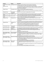
... to determine the bypass-valve-voltage specification. Refer to the documentation supplied by the manufacturer of autopilot-controlled turns. Autopilot Tuning Acceleration Limiter Allows you to limit the speed of your drive unit motor. 26 GHP 12 Installation Instructions Navigation Setup Navigation Gain Allows you to adjust how aggressively the autopilot eliminates cross-track error while following a Route-To pattern. Bypass...
... to determine the bypass-valve-voltage specification. Refer to the documentation supplied by the manufacturer of autopilot-controlled turns. Autopilot Tuning Acceleration Limiter Allows you to limit the speed of your drive unit motor. 26 GHP 12 Installation Instructions Navigation Setup Navigation Gain Allows you to adjust how aggressively the autopilot eliminates cross-track error while following a Route-To pattern. Bypass...

Installation Instructions
Page 31
... and adjust the autopilot configuration. Obtain extensions if necessary. Mount the ECU (page 10). Configure the GHP 12 system by completing the dockside wizard and the sea trial wizard (page 15). Refer to the diagram on page 7 and notes on the GHC 20 data cable to the instructions provided with the drive unit. GHP 12 Installation Instructions 31 Contact Garmin Product Support if you...
... and adjust the autopilot configuration. Obtain extensions if necessary. Mount the ECU (page 10). Configure the GHP 12 system by completing the dockside wizard and the sea trial wizard (page 15). Refer to the diagram on page 7 and notes on the GHC 20 data cable to the instructions provided with the drive unit. GHP 12 Installation Instructions 31 Contact Garmin Product Support if you...


