Maintenance Manual
Page 1
GAD 42 MAINTENANCE MANUAL GARMIN International, Inc. 1200 E. 151st Street Olathe, KS 66062 USA 190-00159-01, Revision A July 2001
GAD 42 MAINTENANCE MANUAL GARMIN International, Inc. 1200 E. 151st Street Olathe, KS 66062 USA 190-00159-01, Revision A July 2001
Maintenance Manual
Page 2
...GAD 42 MAINTENANCE MANUAL P/N 190-00159-01 Page 1 Rev. © Copyright 2001 GARMIN Corporation All Rights Reserved Except as expressly provided below, no part of this manual may be viewed and to print one copy of this manual or of any revision hereto, provided that such electronic or printed copy of this manual... medium to this manual or any purpose without the express prior written consent of any revision to be reproduced, copied, transmitted, disseminated, downloaded or stored in any storage medium, for any revision hereto is strictly prohibited. GARMIN International, Inc. 1200...
...GAD 42 MAINTENANCE MANUAL P/N 190-00159-01 Page 1 Rev. © Copyright 2001 GARMIN Corporation All Rights Reserved Except as expressly provided below, no part of this manual may be viewed and to print one copy of this manual or of any revision hereto, provided that such electronic or printed copy of this manual... medium to this manual or any purpose without the express prior written consent of any revision to be reproduced, copied, transmitted, disseminated, downloaded or stored in any storage medium, for any revision hereto is strictly prohibited. GARMIN International, Inc. 1200...
Maintenance Manual
Page 3
... may not be subject to a penalty of up to 10 years imprisonment and a fine of up to foreign nationals inside or outside of this document. GAD 42 MAINTENANCE MANUAL P/N 190-00159-01 Page 2 Rev.
... may not be subject to a penalty of up to 10 years imprisonment and a fine of up to foreign nationals inside or outside of this document. GAD 42 MAINTENANCE MANUAL P/N 190-00159-01 Page 2 Rev.
Maintenance Manual
Page 4
TABLE OF CONTENTS Paragraph Page 1.0 INTRODUCTION ...4 2.0 REPAIR ...4 3.0 TECHNICAL SPECIFICATIONS 4 4.0 GAD 42 INSTALLATION 4 5.0 GENERAL DESCRIPTION 4 5.1 Analog PC Board 4 5.2 CPU PC Board 5 6.0 BLOCK DIAGRAM 5 7.0 BASIC THEORY OF OPERATION 5 7.1 Power Supplies 5 7.1.1 Power Input Circuitry 5 7.1.2 Main Power Supply 5 7.1.3 Power Supply (+5 V... 10 7.18 King Serial Transmitters 10 7.19 Discrete Inputs 10 7.20 Valid High Inputs 11 7.21 Control Outputs 11 8.0 ASSEMBLY DRAWING 11 1.0 INTRODUCTION GAD 42 MAINTENANCE MANUAL P/N 190-00159-01 Page 3 Rev. A
TABLE OF CONTENTS Paragraph Page 1.0 INTRODUCTION ...4 2.0 REPAIR ...4 3.0 TECHNICAL SPECIFICATIONS 4 4.0 GAD 42 INSTALLATION 4 5.0 GENERAL DESCRIPTION 4 5.1 Analog PC Board 4 5.2 CPU PC Board 5 6.0 BLOCK DIAGRAM 5 7.0 BASIC THEORY OF OPERATION 5 7.1 Power Supplies 5 7.1.1 Power Input Circuitry 5 7.1.2 Main Power Supply 5 7.1.3 Power Supply (+5 V... 10 7.18 King Serial Transmitters 10 7.19 Discrete Inputs 10 7.20 Valid High Inputs 11 7.21 Control Outputs 11 8.0 ASSEMBLY DRAWING 11 1.0 INTRODUCTION GAD 42 MAINTENANCE MANUAL P/N 190-00159-01 Page 3 Rev. A

Maintenance Manual
Page 5
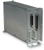
... data from low speed GPS 429 data 2.0 REPAIR The GAD 42 contains no field-repairable components. GAD 42 MAINTENANCE MANUAL P/N 190-00159-01 Page 4 Rev. Return faulty units to GARMIN for service. 3.0 TECHNICAL SPECIFICATIONS Technical specifications for the GAD 42 are listed in the GAD 42 Installation Manual. 5.0 GENERAL DESCRIPTION The GAD 42 Interface Adapter consists of two internal printed circuit board assemblies...
... data from low speed GPS 429 data 2.0 REPAIR The GAD 42 contains no field-repairable components. GAD 42 MAINTENANCE MANUAL P/N 190-00159-01 Page 4 Rev. Return faulty units to GARMIN for service. 3.0 TECHNICAL SPECIFICATIONS Technical specifications for the GAD 42 are listed in the GAD 42 Installation Manual. 5.0 GENERAL DESCRIPTION The GAD 42 Interface Adapter consists of two internal printed circuit board assemblies...
Maintenance Manual
Page 6
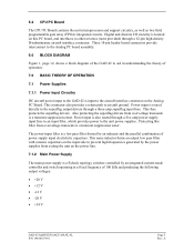
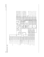
... connectors provide interconnect to the Analog PC board assembly. 6.0 BLOCK DIAGRAM Figure 1, page 12, shows a block diagram of the GAD 42 to prevent high frequencies generated by an integrated current-mode controller and switch operating at a fixed frequency of 100 kHz and producing the... following output voltages: • +20 V • +12 V • -12 V • -20 V • +34 V GAD 42 MAINTENANCE MANUAL P/N 190-00159-01 Page 5 Rev. This same inductor forms an output low pass filter with ceramic capacitors on this filter from overvoltage transients is also...
... connectors provide interconnect to the Analog PC board assembly. 6.0 BLOCK DIAGRAM Figure 1, page 12, shows a block diagram of the GAD 42 to prevent high frequencies generated by an integrated current-mode controller and switch operating at a fixed frequency of 100 kHz and producing the... following output voltages: • +20 V • +12 V • -12 V • -20 V • +34 V GAD 42 MAINTENANCE MANUAL P/N 190-00159-01 Page 5 Rev. This same inductor forms an output low pass filter with ceramic capacitors on this filter from overvoltage transients is also...
Maintenance Manual
Page 7
...output switch from over -voltage transients by transient suppression zeners. 7.3 XYZ Synchro Input Processing Because all XYZ synchro inputs (shown in the GAD 42. All Z synchro inputs are present on the +12 V and -12 V outputs. The snubber circuit conducts current during power interruptions... some of the energy to the power supply input capacitor. The switcher along with filter circuitry produces a smoothed and filtered +5 V. GAD 42 MAINTENANCE MANUAL P/N 190-00159-01 Page 6 Rev. If the power input voltage drops below approximately +8 V, an undervoltage detector turns on a FET...
...output switch from over -voltage transients by transient suppression zeners. 7.3 XYZ Synchro Input Processing Because all XYZ synchro inputs (shown in the GAD 42. All Z synchro inputs are present on the +12 V and -12 V outputs. The snubber circuit conducts current during power interruptions... some of the energy to the power supply input capacitor. The switcher along with filter circuitry produces a smoothed and filtered +5 V. GAD 42 MAINTENANCE MANUAL P/N 190-00159-01 Page 6 Rev. If the power input voltage drops below approximately +8 V, an undervoltage detector turns on a FET...
Maintenance Manual
Page 8
... processed the same way on the CPU PC Board. A dual switching diode clamps over-voltage inputs at every rising edge of the analog-todigital converter. GAD 42 MAINTENANCE MANUAL P/N 190-00159-01 Page 7 Rev. The second circuit that the attenuator output is used as previously described for the D/A converters described later. 7.4 Filter/Attenuator...
... processed the same way on the CPU PC Board. A dual switching diode clamps over-voltage inputs at every rising edge of the analog-todigital converter. GAD 42 MAINTENANCE MANUAL P/N 190-00159-01 Page 7 Rev. The second circuit that the attenuator output is used as previously described for the D/A converters described later. 7.4 Filter/Attenuator...
Maintenance Manual
Page 9
... converter. Full-scale amplitude at D/A converters on each input. 7.9 XYZ Synchro Output Processing Because all XYZ synchro outputs (shown in the GAD 42. A The negative voltages are read by this device for validity checking. Diode clamps protect the A/D inputs from indicators requiring it to not ...CPU PC Board is a 10-channel, 8 bit, serial interface converter. The overall amp gain is used for the same purpose. GAD 42 MAINTENANCE MANUAL P/N 190-00159-01 Page 8 Rev. It is set by the ratio of the signal input to be present during certain operating conditions...
... converter. Full-scale amplitude at D/A converters on each input. 7.9 XYZ Synchro Output Processing Because all XYZ synchro outputs (shown in the GAD 42. A The negative voltages are read by this device for validity checking. Diode clamps protect the A/D inputs from indicators requiring it to not ...CPU PC Board is a 10-channel, 8 bit, serial interface converter. The overall amp gain is used for the same purpose. GAD 42 MAINTENANCE MANUAL P/N 190-00159-01 Page 8 Rev. It is set by the ratio of the signal input to be present during certain operating conditions...
Maintenance Manual
Page 10
...voltage for output by two diodes and two resistors. These devices contain state machine logic that is provided by RS-232 interface when the GAD 42 is shared with the DC A/D converter described previously. 7.15 ARINC 429 Receivers The GPS, NAV, Heading, and Radar Graphics ARINC 429... through two bus transceivers. If A is low, and B is too low, and if the micromonitor latched output fails to toggle indicating CPU lockup. GAD 42 MAINTENANCE MANUAL P/N 190-00159-01 Page 9 Rev. A low power micromonitor watchdog holds the CPU in a serial EEPROM IC on a PNP output transistor. A ...
...voltage for output by two diodes and two resistors. These devices contain state machine logic that is provided by RS-232 interface when the GAD 42 is shared with the DC A/D converter described previously. 7.15 ARINC 429 Receivers The GPS, NAV, Heading, and Radar Graphics ARINC 429... through two bus transceivers. If A is low, and B is too low, and if the micromonitor latched output fails to toggle indicating CPU lockup. GAD 42 MAINTENANCE MANUAL P/N 190-00159-01 Page 9 Rev. A low power micromonitor watchdog holds the CPU in a serial EEPROM IC on a PNP output transistor. A ...

Maintenance Manual
Page 11
... amp. The FPGA output is routed to both a non-inverting and an inverting output amp. This results in order to meet ARINC 429 specifications. GAD 42 MAINTENANCE MANUAL P/N 190-00159-01 Page 10 Rev. 7.16 ARINC 429 Transmitters The GPS Lo-Speed and Hi-speed ARINC 429 transmitters are output from the bus...
... amp. The FPGA output is routed to both a non-inverting and an inverting output amp. This results in order to meet ARINC 429 specifications. GAD 42 MAINTENANCE MANUAL P/N 190-00159-01 Page 10 Rev. 7.16 ARINC 429 Transmitters The GPS Lo-Speed and Hi-speed ARINC 429 transmitters are output from the bus...
Maintenance Manual
Page 12
... a second resistor to turn on the transistor, and the output normally connected to Vcc through a resistor is applied through a discrete input latch. GAD 42 MAINTENANCE MANUAL P/N 190-00159-01 Page 11 Rev. This turns on Q581. When the DIST_IND_OUT latch output from the data bus through a resistor to a ...high inputs are located on the CPU board, and are identical to the output described here. A diode provides transient voltage protection for the GAD 42. This turns the FET on the CPU board, and are identical to ground. The CPU reads this output is grounded, and the ...
... a second resistor to turn on the transistor, and the output normally connected to Vcc through a resistor is applied through a discrete input latch. GAD 42 MAINTENANCE MANUAL P/N 190-00159-01 Page 11 Rev. This turns on Q581. When the DIST_IND_OUT latch output from the data bus through a resistor to a ...high inputs are located on the CPU board, and are identical to the output described here. A diode provides transient voltage protection for the GAD 42. This turns the FET on the CPU board, and are identical to ground. The CPU reads this output is grounded, and the ...
Maintenance Manual
Page 13
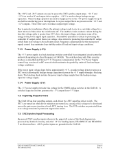
A GAD 42 Block Diagram Page 12 Rev. HEADING X HEADING Y REMOTE CRS SELECT X/COS REMOTE CRS SELECT Y/SIN TRUE AIRSPEED X/SIGNAL TRUE AIRSPEED Y/REFERENCE RESERVED (SPARE X IN) RESERVED (... ARINC 561/568 DATA ARINC 561/568 SYNC DRIVER LEVEL SHIFT ARINC 561/568 CONTINUOUS CLOCK KING SERIAL DATA KING SERIAL CLOCK KING SERIAL SYNC GAD 42 MAINTENANCE MANUAL P/N 190-00159-01 Figure 1.
A GAD 42 Block Diagram Page 12 Rev. HEADING X HEADING Y REMOTE CRS SELECT X/COS REMOTE CRS SELECT Y/SIN TRUE AIRSPEED X/SIGNAL TRUE AIRSPEED Y/REFERENCE RESERVED (SPARE X IN) RESERVED (... ARINC 561/568 DATA ARINC 561/568 SYNC DRIVER LEVEL SHIFT ARINC 561/568 CONTINUOUS CLOCK KING SERIAL DATA KING SERIAL CLOCK KING SERIAL SYNC GAD 42 MAINTENANCE MANUAL P/N 190-00159-01 Figure 1.
Maintenance Manual
Page 14
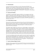
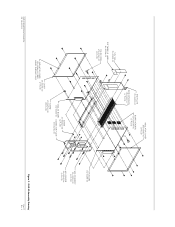
... (2 PLCS) END PLATE 115-00265-00 SIDE EXTRUSION 135-00007-01 (2 PLCS) INSULATOR COVER 250-00064-00 (2 PLCS) BOARD HEADERS 334-00039-00 (3 PLCS) GAD 42 MAINTENANCE MANUAL P/N 190-00159-01 COVER 115-00266-00 INSULATOR COVER (2 PLCS) 250-00064-00 (REF) INSIDE SURFACE ONLY SCREW 211-632340-06 (4 PLCS) ANALOG BOARD 012...-00 SCREW 211-602340-08 (33 PLCS) CPU BOARD 012-00299-00 HEX STANDOFF 214-00004-00 (4 PLCS) HEX SPACER 214-00020-04 (4 PLCS) Figure 2. GAD 42 Assembly Drawing Page 13 Rev.
... (2 PLCS) END PLATE 115-00265-00 SIDE EXTRUSION 135-00007-01 (2 PLCS) INSULATOR COVER 250-00064-00 (2 PLCS) BOARD HEADERS 334-00039-00 (3 PLCS) GAD 42 MAINTENANCE MANUAL P/N 190-00159-01 COVER 115-00266-00 INSULATOR COVER (2 PLCS) 250-00064-00 (REF) INSIDE SURFACE ONLY SCREW 211-632340-06 (4 PLCS) ANALOG BOARD 012...-00 SCREW 211-602340-08 (33 PLCS) CPU BOARD 012-00299-00 HEX STANDOFF 214-00004-00 (4 PLCS) HEX SPACER 214-00020-04 (4 PLCS) Figure 2. GAD 42 Assembly Drawing Page 13 Rev.


