Maintenance Manual
Page 1
GAD 42 MAINTENANCE MANUAL GARMIN International, Inc. 1200 E. 151st Street Olathe, KS 66062 USA 190-00159-01, Revision A July 2001
GAD 42 MAINTENANCE MANUAL GARMIN International, Inc. 1200 E. 151st Street Olathe, KS 66062 USA 190-00159-01, Revision A July 2001
Maintenance Manual
Page 2
Insertion Date By GAD 42 MAINTENANCE MANUAL P/N 190-00159-01 Page 1 Rev. A GARMIN Corporation grants permission to download a single copy of this manual and of any revision to this manual onto a hard drive or other electronic storage medium to be viewed and to print one copy of this manual or of any revision hereto, provided that such electronic or printed copy...
Insertion Date By GAD 42 MAINTENANCE MANUAL P/N 190-00159-01 Page 1 Rev. A GARMIN Corporation grants permission to download a single copy of this manual and of any revision to this manual onto a hard drive or other electronic storage medium to be viewed and to print one copy of this manual or of any revision hereto, provided that such electronic or printed copy...
Maintenance Manual
Page 3
... of up to foreign nationals inside or outside of the United States without first obtaining an export license. GAD 42 MAINTENANCE MANUAL P/N 190-00159-01 Page 2 Rev. LIST OF EFFECTIVE PAGES Page 1 2 3 4 5 6 7 8 9 10 11 12 13 Revision A A A A A A A A A A A A A INFORMATION SUBJECT TO EXPORT CONTROL LAWS This document may contain information which is subject to the Export Administration Regulations ("EAR") issued...
... of up to foreign nationals inside or outside of the United States without first obtaining an export license. GAD 42 MAINTENANCE MANUAL P/N 190-00159-01 Page 2 Rev. LIST OF EFFECTIVE PAGES Page 1 2 3 4 5 6 7 8 9 10 11 12 13 Revision A A A A A A A A A A A A A INFORMATION SUBJECT TO EXPORT CONTROL LAWS This document may contain information which is subject to the Export Administration Regulations ("EAR") issued...
Maintenance Manual
Page 4
... 7 7.9 XYZ Synchro Output Processing 8 7.10 Digital-to-Analog Converter 8 7.11 Output Amplifiers 8 7.12 CPU Circuitry ...9 7.13 FPGA Devices 9 7.14 Serial EEPROM 9 7.15 ARINC 429 Receivers 9 7.16 ARINC Transmitters 10 7.17 ARINC 561/568 Transmitters 10 7.18 King Serial Transmitters 10 7.19 Discrete Inputs 10 7.20 Valid High Inputs 11 7.21 Control Outputs 11 8.0 ASSEMBLY DRAWING 11 1.0 INTRODUCTION GAD 42 MAINTENANCE MANUAL P/N 190-00159-01...
... 7 7.9 XYZ Synchro Output Processing 8 7.10 Digital-to-Analog Converter 8 7.11 Output Amplifiers 8 7.12 CPU Circuitry ...9 7.13 FPGA Devices 9 7.14 Serial EEPROM 9 7.15 ARINC 429 Receivers 9 7.16 ARINC Transmitters 10 7.17 ARINC 561/568 Transmitters 10 7.18 King Serial Transmitters 10 7.19 Discrete Inputs 10 7.20 Valid High Inputs 11 7.21 Control Outputs 11 8.0 ASSEMBLY DRAWING 11 1.0 INTRODUCTION GAD 42 MAINTENANCE MANUAL P/N 190-00159-01...

Maintenance Manual
Page 5
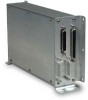
... King serial data from GPS 429 data • Output high speed 429 data from low speed GPS 429 data 2.0 REPAIR The GAD 42 contains no field-repairable components. Return faulty units to GARMIN for service. 3.0 TECHNICAL SPECIFICATIONS Technical specifications for the GAD 42 are listed in the GAD 42 Installation Manual, P/N 190-00159-00. 4.0 GAD 42 INSTALLATION Installation information for the unit is a microprocessor based input/output (I /O circuitry. A 44-pin high-density D-subminiature aircraft interface connector provides interfaces to Garmin long-range navigation products. The GAD 42...
... King serial data from GPS 429 data • Output high speed 429 data from low speed GPS 429 data 2.0 REPAIR The GAD 42 contains no field-repairable components. Return faulty units to GARMIN for service. 3.0 TECHNICAL SPECIFICATIONS Technical specifications for the GAD 42 are listed in the GAD 42 Installation Manual, P/N 190-00159-00. 4.0 GAD 42 INSTALLATION Installation information for the unit is a microprocessor based input/output (I /O circuitry. A 44-pin high-density D-subminiature aircraft interface connector provides interfaces to Garmin long-range navigation products. The GAD 42...
Maintenance Manual
Page 6
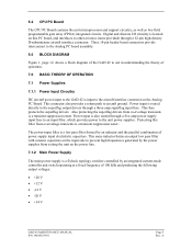
... the aircraft interface connector on this filter from overvoltage transients is a low pass filter formed by an integrated current-mode controller and switch operating at a fixed frequency of 100 kHz and producing the following output voltages: • +20 V • +12 V • -12 V • -20 V • +34 V GAD 42 MAINTENANCE MANUAL P/N 190-00159-01 Page 5 Rev. Power input is routed directly to prevent high frequencies generated by the power supplies...
... the aircraft interface connector on this filter from overvoltage transients is a low pass filter formed by an integrated current-mode controller and switch operating at a fixed frequency of 100 kHz and producing the following output voltages: • +20 V • +12 V • -12 V • -20 V • +34 V GAD 42 MAINTENANCE MANUAL P/N 190-00159-01 Page 5 Rev. Power input is routed directly to prevent high frequencies generated by the power supplies...
Maintenance Manual
Page 7
... an integrated circuit controller and switch operating at a fixed frequency of the block diagram) are processed by identical circuitry, only the 11.8 Vac heading inputs, HEADING X and HEADING Y are discussed here. The snubber circuit conducts current during power interruptions. The snubber operation is critical to protecting the controller IC output switch from +5 V input. 7.2 Superflag Output Drivers The GAD 42 has four superflag outputs, each FET, turning it on , causing...
... an integrated circuit controller and switch operating at a fixed frequency of the block diagram) are processed by identical circuitry, only the 11.8 Vac heading inputs, HEADING X and HEADING Y are discussed here. The snubber circuit conducts current during power interruptions. The snubber operation is critical to protecting the controller IC output switch from +5 V input. 7.2 Superflag Output Drivers The GAD 42 has four superflag outputs, each FET, turning it on , causing...
Maintenance Manual
Page 8
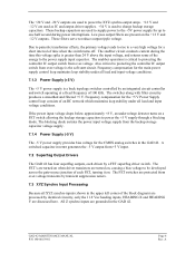
... circuit that the attenuator output is applied to the control input of the block diagram) are processed the same way on the CPU PC Board. GAD 42 MAINTENANCE MANUAL P/N 190-00159-01 Page 7 Rev. The differential amplifier attenuates the reference-input signals. All other 26 Vac reference inputs are processed by an RC circuit. The output is used to monitor the AC reference input amplitude, and also...
... circuit that the attenuator output is applied to the control input of the block diagram) are processed the same way on the CPU PC Board. GAD 42 MAINTENANCE MANUAL P/N 190-00159-01 Page 7 Rev. The differential amplifier attenuates the reference-input signals. All other 26 Vac reference inputs are processed by an RC circuit. The output is used to monitor the AC reference input amplitude, and also...
Maintenance Manual
Page 9
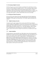
... of the block diagram) are amplified by this output. Control loop stability is possible due to higher impedance loads being driven by the output amp. 7.11 Output Amplifiers The output amps use a unity-gain buffer amp, a high-voltage op-amp, and inverting push-pull Darlington driver transistors all XYZ synchro outputs (shown in the GAD 42. All 26 Vac reference inputs are protected from...
... of the block diagram) are amplified by this output. Control loop stability is possible due to higher impedance loads being driven by the output amp. 7.11 Output Amplifiers The output amps use a unity-gain buffer amp, a high-voltage op-amp, and inverting push-pull Darlington driver transistors all XYZ synchro outputs (shown in the GAD 42. All 26 Vac reference inputs are protected from...
Maintenance Manual
Page 10
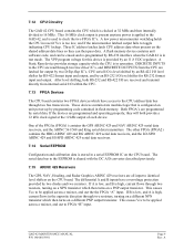
... I /O level shifter for output by RS-232 interface when the GAD 42 is in flash memory. The differential A and B inputs have access to FPGA "B" input. If B is low, and A is high, current flows in a serial EEPROM IC on unit power-up by an 11.8 VDC regulator. A Static Ram device provides storage capacity while the CPU is in reset if Vcc is too...
... I /O level shifter for output by RS-232 interface when the GAD 42 is in flash memory. The differential A and B inputs have access to FPGA "B" input. If B is low, and A is high, current flows in a serial EEPROM IC on unit power-up by an 11.8 VDC regulator. A Static Ram device provides storage capacity while the CPU is in reset if Vcc is too...

Maintenance Manual
Page 11
... high-frequency attenuation is routed to the output amp. During the time between data bits, the FPGA output is open or connected to meet ARINC 429 specifications. The transition edges are located on the CPU board. From here, the signal is provided by a King serial request (KING_SERIAL_RQST) input going to logic low. 7.19 Discrete Inputs All discrete inputs are rounded by a different set the gain...
... high-frequency attenuation is routed to the output amp. During the time between data bits, the FPGA output is open or connected to meet ARINC 429 specifications. The transition edges are located on the CPU board. From here, the signal is provided by a King serial request (KING_SERIAL_RQST) input going to logic low. 7.19 Discrete Inputs All discrete inputs are rounded by a different set the gain...
Maintenance Manual
Page 12
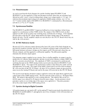
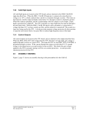
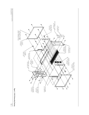
... aircraft power voltage over -current protection. When the HDG_VALID_HI input pin is open, grounded, or connected to ground, turning it off . A A zener provides transient protection for the FET. 8.0 ASSEMBLY DRAWING Figure 2, page 13, shows an assembly drawing (with part numbers) for the transistor. When this as a logic high from the CPU data bus is at the input. 7.21 Control Outputs All control outputs are located...
... aircraft power voltage over -current protection. When the HDG_VALID_HI input pin is open, grounded, or connected to ground, turning it off . A A zener provides transient protection for the FET. 8.0 ASSEMBLY DRAWING Figure 2, page 13, shows an assembly drawing (with part numbers) for the transistor. When this as a logic high from the CPU data bus is at the input. 7.21 Control Outputs All control outputs are located...
Maintenance Manual
Page 13
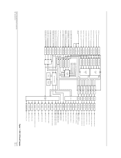
HEADING X HEADING Y REMOTE CRS SELECT X/COS REMOTE CRS SELECT Y/SIN TRUE AIRSPEED X/SIGNAL TRUE AIRSPEED Y/REFERENCE RESERVED (SPARE X IN) RESERVED (SPARE Y IN) 11-33 VDC AIRCRAFT PWR/GND 26 VAC ...GPS ARINC 429 OUT A GPS ARINC 429 OUT B HIGH SPEED ARINC 429 OUT A HIGH SPEED ARINC 429 OUT B DISTANCE INDICATOR CONTROL FPGA ENCODE LOGIC SELECTED CRS CONTROL ARINC 561/568 CLOCK ARINC 561/568 DATA ARINC 561/568 SYNC DRIVER LEVEL SHIFT ARINC 561/568 CONTINUOUS CLOCK KING SERIAL DATA KING SERIAL CLOCK KING SERIAL SYNC GAD 42 MAINTENANCE MANUAL P/N 190-00159-01 Figure 1. GAD 42 Block Diagram...
HEADING X HEADING Y REMOTE CRS SELECT X/COS REMOTE CRS SELECT Y/SIN TRUE AIRSPEED X/SIGNAL TRUE AIRSPEED Y/REFERENCE RESERVED (SPARE X IN) RESERVED (SPARE Y IN) 11-33 VDC AIRCRAFT PWR/GND 26 VAC ...GPS ARINC 429 OUT A GPS ARINC 429 OUT B HIGH SPEED ARINC 429 OUT A HIGH SPEED ARINC 429 OUT B DISTANCE INDICATOR CONTROL FPGA ENCODE LOGIC SELECTED CRS CONTROL ARINC 561/568 CLOCK ARINC 561/568 DATA ARINC 561/568 SYNC DRIVER LEVEL SHIFT ARINC 561/568 CONTINUOUS CLOCK KING SERIAL DATA KING SERIAL CLOCK KING SERIAL SYNC GAD 42 MAINTENANCE MANUAL P/N 190-00159-01 Figure 1. GAD 42 Block Diagram...
Maintenance Manual
Page 14
S/N TAG 161-00269-00 SOFTWARE ID LABEL 161-20306-00 NYLON KNOB 430-00021-00 (2 PLCS) END PLATE 115-00265-00 SIDE EXTRUSION 135-00007-01 (2 PLCS) INSULATOR COVER 250-00064-00 (2 PLCS) BOARD HEADERS 334-00039-00 (3 PLCS) GAD 42 MAINTENANCE MANUAL P/N 190-00159-01 COVER 115-00266-00 INSULATOR COVER (2 ...PLCS) 250-00064-00 (REF) INSIDE SURFACE ONLY SCREW 211-632340-06 (4 PLCS) ANALOG BOARD 012-00300-00 CONNECTOR PLATE 015-00264-00 SCREW 211-602340-08 (33 PLCS) ...
S/N TAG 161-00269-00 SOFTWARE ID LABEL 161-20306-00 NYLON KNOB 430-00021-00 (2 PLCS) END PLATE 115-00265-00 SIDE EXTRUSION 135-00007-01 (2 PLCS) INSULATOR COVER 250-00064-00 (2 PLCS) BOARD HEADERS 334-00039-00 (3 PLCS) GAD 42 MAINTENANCE MANUAL P/N 190-00159-01 COVER 115-00266-00 INSULATOR COVER (2 ...PLCS) 250-00064-00 (REF) INSIDE SURFACE ONLY SCREW 211-632340-06 (4 PLCS) ANALOG BOARD 012-00300-00 CONNECTOR PLATE 015-00264-00 SCREW 211-602340-08 (33 PLCS) ...


