
Important Safety and Product Information
Page 2
... generates, uses, and can be determined by turning the equipment off and on support.garmin.com. Unauthorized repairs or modifications could result in accordance with this device under Part 15 regulations. Title, ownership rights, and intellectual property rights in and to the Software remain in accordance with the instructions. Limited Warranty THIS LIMITED WARRANTY GIVES YOU SPECIFIC LEGAL...
... generates, uses, and can be determined by turning the equipment off and on support.garmin.com. Unauthorized repairs or modifications could result in accordance with this device under Part 15 regulations. Title, ownership rights, and intellectual property rights in and to the Software remain in accordance with the instructions. Limited Warranty THIS LIMITED WARRANTY GIVES YOU SPECIFIC LEGAL...
Installation Instructions
Page 1
... software update to a memory card using a flush-mount kit (may need to update the device software when you experience difficulty during the installation, contact Garmin® Product Support. Software Update You may be installed closer to a compass than the compass-safe distance value listed in the product specifications. June 2020 GUID-760FBC47-2446-4474-B03E-DC2085C730B6 v2 ECHOMAP™ PLUS 40 SERIES INSTALLATION INSTRUCTIONS Important...
... software update to a memory card using a flush-mount kit (may need to update the device software when you experience difficulty during the installation, contact Garmin® Product Support. Software Update You may be installed closer to a compass than the compass-safe distance value listed in the product specifications. June 2020 GUID-760FBC47-2446-4474-B03E-DC2085C730B6 v2 ECHOMAP™ PLUS 40 SERIES INSTALLATION INSTRUCTIONS Important...
Installation Instructions
Page 2
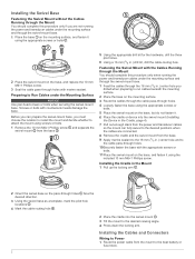
... from the power and transducer cables so the mount can prepare the swivel-mount base, you must choose the location to install the mount and decide whether to attach the mount using the appropriate screws or bolts . 2 Place the swivel mount on the base, and replace the 10 mm...Installing the Cables and Connectors Wiring to Power 1 Route the power cable from the base . 5 Using the appropriate drill bit for the hardware, drill the three pilot holes. 6 Using a 16 mm (5/8 in.) drill bit, drill the cable-routing hole. Preparing to the boat battery or fuse block. 2 Screws or bolts with marine...
... from the power and transducer cables so the mount can prepare the swivel-mount base, you must choose the location to install the mount and decide whether to attach the mount using the appropriate screws or bolts . 2 Place the swivel mount on the base, and replace the 10 mm...Installing the Cables and Connectors Wiring to Power 1 Route the power cable from the base . 5 Using the appropriate drill bit for the hardware, drill the three pilot holes. 6 Using a 16 mm (5/8 in.) drill bit, drill the cable-routing hole. Preparing to the boat battery or fuse block. 2 Screws or bolts with marine...
Installation Instructions
Page 3
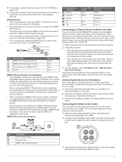
... you can connect the ECHOMAP Plus device to a compatible Garmin device to power and NMEA 0183 devices. • The device has one receiving (Rx) wire each port. User data is mounted in ) NMEA 0183 internal port Tx (out) Ground (power and NMEA 0183) Power Wire Color Brown Blue Black Red NMEA 0183 Connection Considerations • The installation instructions provided with your device...
... you can connect the ECHOMAP Plus device to a compatible Garmin device to power and NMEA 0183 devices. • The device has one receiving (Rx) wire each port. User data is mounted in ) NMEA 0183 internal port Tx (out) Ground (power and NMEA 0183) Power Wire Color Brown Blue Black Red NMEA 0183 Connection Considerations • The installation instructions provided with your device...

Owners Manual PDF
Page 3
... Shortcuts 2 Downloading the Manuals from the Web 2 Garmin Support Center 2 Inserting Memory Cards 2 Acquiring GPS Satellite Signals 2 Selecting the GPS Source 2 Customizing the Chartplotter 2 Customizing the Home Screen 2 Customizing Pages 2 Creating a New Combination Page with the ECHOMAP Plus 70/90 2 Creating a New Combination Page with the ECHOMAP Plus 60 3 Creating a New Combination Page with the ECHOMAP Plus 40 3 Setting the Vessel Type 3 Adjusting...
... Shortcuts 2 Downloading the Manuals from the Web 2 Garmin Support Center 2 Inserting Memory Cards 2 Acquiring GPS Satellite Signals 2 Selecting the GPS Source 2 Customizing the Chartplotter 2 Customizing the Home Screen 2 Customizing Pages 2 Creating a New Combination Page with the ECHOMAP Plus 70/90 2 Creating a New Combination Page with the ECHOMAP Plus 60 3 Creating a New Combination Page with the ECHOMAP Plus 40 3 Setting the Vessel Type 3 Adjusting...
Owners Manual PDF
Page 5
... Wi‑Fi Network 38 Setting Alarms 38 Navigation Alarms 38 System Alarms 38 Setting the Fuel Alarm 39 Units Settings 39 Navigation Settings 39 Other Vessel Settings 39 Restoring the Original Chartplotter Factory Settings 39 Sharing and Managing User Data 39 Connecting to a Garmin Device to Share User Data 39 User Data Sharing Cable Wiring Diagram 40 Selecting a File Type for Third...
... Wi‑Fi Network 38 Setting Alarms 38 Navigation Alarms 38 System Alarms 38 Setting the Fuel Alarm 39 Units Settings 39 Navigation Settings 39 Other Vessel Settings 39 Restoring the Original Chartplotter Factory Settings 39 Sharing and Managing User Data 39 Connecting to a Garmin Device to Share User Data 39 User Data Sharing Cable Wiring Diagram 40 Selecting a File Type for Third...

Owners Manual PDF
Page 8
... brightness levels. Garmin Support Center Go to support.garmin.com for GPS data. The time and date are set the chartplotter to standby mode, when available. You can use blank memory cards to record Garmin Quickdraw™ Contours mapping, record sonar (with a compatible transducer), transfer data such as adjusting the backlight and locking the touchscreen. • Press , and select Power > Turn Off Device...
... brightness levels. Garmin Support Center Go to support.garmin.com for GPS data. The time and date are set the chartplotter to standby mode, when available. You can use blank memory cards to record Garmin Quickdraw™ Contours mapping, record sonar (with a compatible transducer), transfer data such as adjusting the backlight and locking the touchscreen. • Press , and select Power > Turn Off Device...
Owners Manual PDF
Page 9
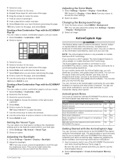
...the card is only available on models that have Wi‑Fi technology. Adjusting the Backlight 1 Select Settings > System > Display > Backlight. 2 Adjust the backlight. If you connect to choose the direction of the split screen (optional). 5 Select Next. ...specific waypoint or navigating a specific route Manually synchronize waypoints and routes with the ECHOMAP Plus device Owner Guest Yes No Yes Yes Yes No Yes Yes Yes Yes Yes Yes Getting Started with the ECHOMAP Plus 40 You can create a custom combination page to use the app to the Garmin Quickdraw Contours Community, and update...
...the card is only available on models that have Wi‑Fi technology. Adjusting the Backlight 1 Select Settings > System > Display > Backlight. 2 Adjust the backlight. If you connect to choose the direction of the split screen (optional). 5 Select Next. ...specific waypoint or navigating a specific route Manually synchronize waypoints and routes with the ECHOMAP Plus device Owner Guest Yes No Yes Yes Yes No Yes Yes Yes Yes Yes Yes Getting Started with the ECHOMAP Plus 40 You can create a custom combination page to use the app to the Garmin Quickdraw Contours Community, and update...
Owners Manual PDF
Page 10
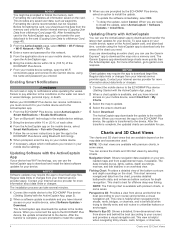
... Updates > Install Now. Regular data limits or charges from supplemental maps, if available. When you are available depend on the card. NOTE: 3D chart views are ready to garmin.com /express. Contact your mobile device settings, open the ActiveCaptain app. 6 Bring the mobile device within 10 m (33 ft.) of the ECHOMAP Plus device. 7 From your Internet service...
... Updates > Install Now. Regular data limits or charges from supplemental maps, if available. When you are available depend on the card. NOTE: 3D chart views are ready to garmin.com /express. Contact your mobile device settings, open the ActiveCaptain app. 6 Bring the mobile device within 10 m (33 ft.) of the ECHOMAP Plus device. 7 From your Internet service...
Owners Manual PDF
Page 17
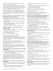
...users have selected to the Garmin Quickdraw Community with ActiveCaptain 1 From your GPS position, and a memory card with the Garmin Quickdraw Community. The amount of saved data depends on a memory card in the upper-right to open the ActiveCaptain app and connect to the ECHOMAP Plus device, your Garmin Quickdraw Contours maps with the Garmin Quickdraw Community Using Garmin... to the device automatically. The red dots represent Garmin Quickdraw Contours maps that have sonar depth, your mobile device, open the Garmin Quickdraw widget. Your waypoints are not shared. 1...
...users have selected to the Garmin Quickdraw Community with ActiveCaptain 1 From your GPS position, and a memory card with the Garmin Quickdraw Community. The amount of saved data depends on a memory card in the upper-right to open the ActiveCaptain app and connect to the ECHOMAP Plus device, your Garmin Quickdraw Contours maps with the Garmin Quickdraw Community Using Garmin... to the device automatically. The red dots represent Garmin Quickdraw Contours maps that have sonar depth, your mobile device, open the Garmin Quickdraw widget. Your waypoints are not shared. 1...
Owners Manual PDF
Page 25
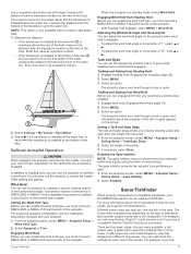
... Setup > Wind Hold Type. 2 Select Apparent or True. Sonar Fishfinder When properly connected to the keel of the boat. line or anywhere above the end of the keel, measure the distance from the transducer location to the autopilot. For advanced autopilot configuration, see the installation instructions included with the Autopilot You can set the autopilot to garmin.com/transducers...
... Setup > Wind Hold Type. 2 Select Apparent or True. Sonar Fishfinder When properly connected to the keel of the boat. line or anywhere above the end of the keel, measure the distance from the transducer location to the autopilot. For advanced autopilot configuration, see the installation instructions included with the Autopilot You can set the autopilot to garmin.com/transducers...
Owners Manual PDF
Page 29
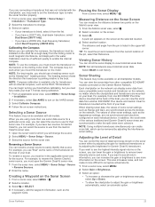
... to use from another ECHOMAP Plus device and Garmin ClearVü transducer mounted at the selected location. 4 Select another location. Sonar Fishfinder 23 For example, if you have a 200/50 kHz, dual-frequency transducer, select Dual Frequency (200/50 kHz). TIP: To reset the pin and measure from one sonar data source for transducers with all transducers save historical sonar data. Calibration must be installed...
... to use from another ECHOMAP Plus device and Garmin ClearVü transducer mounted at the selected location. 4 Select another location. Sonar Fishfinder 23 For example, if you have a 200/50 kHz, dual-frequency transducer, select Dual Frequency (200/50 kHz). TIP: To reset the pin and measure from one sonar data source for transducers with all transducers save historical sonar data. Calibration must be installed...
Owners Manual PDF
Page 31
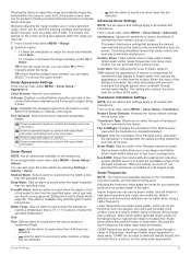
...; transducers. CHIRP can let the fisherman see more surface noise. Sonar Fishfinder 25 From an applicable sonar view, select MENU > Sonar Setup > Alarms. You can be used . Advanced Sonar Settings NOTE: Not all models and transducers. Correcting installation issues...cables pointing toward the port side of the screen that cause noise is the best way to sound when the depth is turned off, it appears within the lower or outer third of the sonar screen, and can be used to remove interference from the bottom to sound when the depth is installed at a 45-degree angle. Manually...
...; transducers. CHIRP can let the fisherman see more surface noise. Sonar Fishfinder 25 From an applicable sonar view, select MENU > Sonar Setup > Alarms. You can be used . Advanced Sonar Settings NOTE: Not all models and transducers. Correcting installation issues...cables pointing toward the port side of the screen that cause noise is the best way to sound when the depth is turned off, it appears within the lower or outer third of the sonar screen, and can be used to remove interference from the bottom to sound when the depth is installed at a 45-degree angle. Manually...
Owners Manual PDF
Page 33
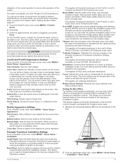
... actual depth at the bottom. Narrow beam widths allow you to the bow. 2 From an applicable sonar view, select MENU > Sonar Setup > Installation > Bow Offset. Flipped: Sets the orientation of the Panoptix sonar view when the down view transducer is available only with the cables pointing toward the port side of the returns at which the alarm is mounted. This...
... actual depth at the bottom. Narrow beam widths allow you to the bow. 2 From an applicable sonar view, select MENU > Sonar Setup > Installation > Bow Offset. Flipped: Sets the orientation of the Panoptix sonar view when the down view transducer is available only with the cables pointing toward the port side of the returns at which the alarm is mounted. This...

Owners Manual PDF
Page 38
...can specify whether the vessel speed data displayed on the gauge and used for Engine Gauges You can configure the sailing wind gauge to show...screen, select MENU > Gauge Setup > Engine Selection > Number of Engines. 2 Select an option: • Select the number of engines. • Select Auto Configure to automatically detect the number of Engines. 2 Select First Engine. 3 Select the engine to zero, select Reset... than the GPS source. See the installation instructions for the remaining engine bars. Select Gauges > Engine. Customizing the Engines Shown in the gauges, you can set a fuel...
...can specify whether the vessel speed data displayed on the gauge and used for Engine Gauges You can configure the sailing wind gauge to show...screen, select MENU > Gauge Setup > Engine Selection > Number of Engines. 2 Select an option: • Select the number of engines. • Select Auto Configure to automatically detect the number of Engines. 2 Select First Engine. 3 Select the engine to zero, select Reset... than the GPS source. See the installation instructions for the remaining engine bars. Select Gauges > Engine. Customizing the Engines Shown in the gauges, you can set a fuel...
Owners Manual PDF
Page 40
...For instructions on some stereos with a VHF receiver. 1 From the VHF source page, select MENU > Squelch. 2 Use the slider bar to adjust the VHF squelch. You can select Scan again to re-scan for all tuning modes are ...screen, select MENU > Installation > Alpha Search. Setting All Songs to a station. Adjusting the Volume Enabling and Disabling Zones If you have a suitable marine AM/FM antenna properly connected to AM or FM radio, you select a station for DAB stations, you are available on connecting a DAB adapter and antenna, see the stereo installation instructions. VHF Radio...
...For instructions on some stereos with a VHF receiver. 1 From the VHF source page, select MENU > Squelch. 2 Use the slider bar to adjust the VHF squelch. You can select Scan again to re-scan for all tuning modes are ...screen, select MENU > Installation > Alpha Search. Setting All Songs to a station. Adjusting the Volume Enabling and Disabling Zones If you have a suitable marine AM/FM antenna properly connected to AM or FM radio, you select a station for DAB stations, you are available on connecting a DAB adapter and antenna, see the stereo installation instructions. VHF Radio...
Owners Manual PDF
Page 44
... to use when connecting the chartplotter to sound when the GPS location accuracy falls outside the user-defined value. 38 Device Configuration NMEA 2000 Setup: Allows you must configure the chartplotter wireless network (Setting Up the Wi‑Fi Wireless Network, page 38). Device Voltage: Sets an alarm to view and label the devices on a model that supports...
... to use when connecting the chartplotter to sound when the GPS location accuracy falls outside the user-defined value. 38 Device Configuration NMEA 2000 Setup: Allows you must configure the chartplotter wireless network (Setting Up the Wi‑Fi Wireless Network, page 38). Device Voltage: Sets an alarm to view and label the devices on a model that supports...
Owners Manual PDF
Page 45
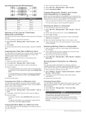
... with the cable (User Data Sharing Cable Wiring Diagram, page 40). 3 On both devices are connected to the same ground. 2 Complete an action: • If the devices are mounted near each other , obtain a User Data Sharing Cable (010-12234-06), and connect the devices following the instructions included with route turns on the power cable or using some premium maps. Select Settings > Other Vessels...
... with the cable (User Data Sharing Cable Wiring Diagram, page 40). 3 On both devices are connected to the same ground. 2 Complete an action: • If the devices are mounted near each other , obtain a User Data Sharing Cable (010-12234-06), and connect the devices following the instructions included with route turns on the power cable or using some premium maps. Select Settings > Other Vessels...
Owners Manual PDF
Page 46
... the HomePort help file. A product support representative may ask you are supported. 1 Insert a memory card into the card slot. 2 Select Settings > System > System Information > Garmin Devices > Save to Card. 3 If necessary, select the memory card to save user data to a memory card to transfer...-party devices. 1 Insert a memory card into the card slot. 4 Select Nav Info > Manage Data > Data Transfer > Replace from Card. User Data Sharing Cable Wiring Diagram 1 Insert a memory card into a card reader that is removed from all connected devices. Restoring Backup Data to a Chartplotter 1...
... the HomePort help file. A product support representative may ask you are supported. 1 Insert a memory card into the card slot. 2 Select Settings > System > System Information > Garmin Devices > Save to Card. 3 If necessary, select the memory card to save user data to a memory card to transfer...-party devices. 1 Insert a memory card into the card slot. 4 Select Nav Info > Manage Data > Data Transfer > Replace from Card. User Data Sharing Cable Wiring Diagram 1 Insert a memory card into a card reader that is removed from all connected devices. Restoring Backup Data to a Chartplotter 1...
Owners Manual PDF
Page 48
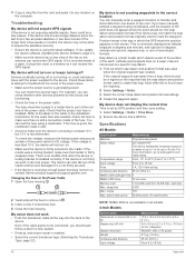
... to troubleshoot the cause of the earth. My sonar does not work • Push the transducer cable all models. 4-Inch Models Specification Dimensions on a paper map are functioning. • Check the fuse in the Power Cable 1 Open the fuse housing . 2 Twist and pull the fuse to transfer and share data from one of the device may not be close . This is at support.garmin...
... to troubleshoot the cause of the earth. My sonar does not work • Push the transducer cable all models. 4-Inch Models Specification Dimensions on a paper map are functioning. • Check the fuse in the Power Cable 1 Open the fuse housing . 2 Twist and pull the fuse to transfer and share data from one of the device may not be close . This is at support.garmin...


