Manual/User Guide
Page 1
C141-E262 3-1 CHAPTER 3 Installation Conditions 3.1 Dimensions 3.2 Mounting 3.3 Connections with Host System This chapter gives the external dimensions, installation conditions, surface temperature conditions, cable connections, and switch settings of the hard disk drives.
C141-E262 3-1 CHAPTER 3 Installation Conditions 3.1 Dimensions 3.2 Mounting 3.3 Connections with Host System This chapter gives the external dimensions, installation conditions, surface temperature conditions, cable connections, and switch settings of the hard disk drives.
Manual/User Guide
Page 2
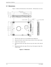
All dimensions are in mm. *1 The PCA and connectors are not included in these dimensions. *2 Dimension from the center of the user tap to the base of the connector pins *3 Length of the connector pins *4 Dimension from the outer edge of the user tap to the center of the connector pins *5 Dimension from the outer edge of the user tap to the innermost edge of the disk drive. Installation Conditions 3.1 Dimensions Figure 3.1 illustrates the dimensions of the connector pins Figure 3.1 Dimensions 3-2 C141-E262
All dimensions are in mm. *1 The PCA and connectors are not included in these dimensions. *2 Dimension from the center of the user tap to the base of the connector pins *3 Length of the connector pins *4 Dimension from the outer edge of the user tap to the center of the connector pins *5 Dimension from the outer edge of the user tap to the innermost edge of the disk drive. Installation Conditions 3.1 Dimensions Figure 3.1 illustrates the dimensions of the connector pins Figure 3.1 Dimensions 3-2 C141-E262
Manual/User Guide
Page 4
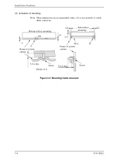
if it is not possible to satisfy them, contact us. Installation Conditions (3) Limitation of A 3.0 or less Screw Figure 3.2 Mounting frame structure 3-4 C141-E262 Bottom surface mounting DE 2 A Frame of system cabinet 2.5 2.5 2.5 Side surface 2.5 mounting PCA B Frame of system cabinet 3.0 or less Screw Details of mounting Note) These dimensions are recommended values;
if it is not possible to satisfy them, contact us. Installation Conditions (3) Limitation of A 3.0 or less Screw Figure 3.2 Mounting frame structure 3-4 C141-E262 Bottom surface mounting DE 2 A Frame of system cabinet 2.5 2.5 2.5 Side surface 2.5 mounting PCA B Frame of system cabinet 3.0 or less Screw Details of mounting Note) These dimensions are recommended values;