Manual/User Guide
Page 3
... 3-3 The tightening torque must be mounted in Figure 3.2. 3.2 Mounting 3.2 Mounting For information on mounting, see the "FUJITSU 2.5-INCH HDD INTEGRATION GUIDANCE (C141-E144)." (1) Orientation The disk drives can be 0.49N•m (5kgf•cm). When attaching the HDD to the system frame, do not allow the system frame to touch parts (cover and base...). Use M3 screw for the mounting screw and the screw length should satisfy the specification in any direction. (2) Frame The MR head bias of the HDD disk enclosure (DE) is attached.
... 3-3 The tightening torque must be mounted in Figure 3.2. 3.2 Mounting 3.2 Mounting For information on mounting, see the "FUJITSU 2.5-INCH HDD INTEGRATION GUIDANCE (C141-E144)." (1) Orientation The disk drives can be 0.49N•m (5kgf•cm). When attaching the HDD to the system frame, do not allow the system frame to touch parts (cover and base...). Use M3 screw for the mounting screw and the screw length should satisfy the specification in any direction. (2) Frame The MR head bias of the HDD disk enclosure (DE) is attached.
Manual/User Guide
Page 5
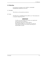
3.2 Mounting Because of breather hole mounted to the HDD, do not allow this to block. For breather hole of Figure 3.3, at least, do not allow its around φ 3 to close during mounting. Figure 3.3 Location of breather hole is shown as Figure 3.3. Locating of breather C141-E262 3-5
3.2 Mounting Because of breather hole mounted to the HDD, do not allow this to block. For breather hole of Figure 3.3, at least, do not allow its around φ 3 to close during mounting. Figure 3.3 Location of breather hole is shown as Figure 3.3. Locating of breather C141-E262 3-5
Manual/User Guide
Page 7
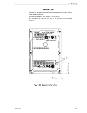
... not touch the printed circuit board, but hold it too hard, the cover and the spindle motor contact, which may cause damage to the disk drive. Damage: Do not press the cover of the disk drive. Ensure that the disk drive is not affected by the edges. (6) Handling cautions Please ...keep the following cautions, and handle the HDD under the safety environment. 3.2 Mounting (5) Service area Figure...
... not touch the printed circuit board, but hold it too hard, the cover and the spindle motor contact, which may cause damage to the disk drive. Damage: Do not press the cover of the disk drive. Ensure that the disk drive is not affected by the edges. (6) Handling cautions Please ...keep the following cautions, and handle the HDD under the safety environment. 3.2 Mounting (5) Service area Figure...
Manual/User Guide
Page 8
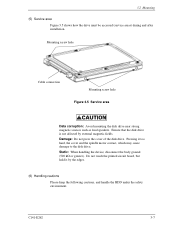
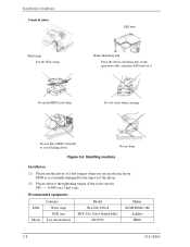
ESD mat Shock absorbing mat Place the shock absorbing mat on the operation table, and place ESD mat on it. Do not drop. HDD is occasionally damaged by the impact of the driver. (2) Please observe the tightening torque of a low impact when you use the driver of .... Figure 3.6 Handling cautions - Do not stack when carrying. M3 0.49N • m (5 kgf • cm). - Installation (1) Please use an electric driver. Do not hit HDD each other. Recommended equipments ESD Shock Contents Wrist strap ESD mat Low shock driver Model JX-1200-3056-8 SKY-8A (Color Seiden Mat) SS-6500...
ESD mat Shock absorbing mat Place the shock absorbing mat on the operation table, and place ESD mat on it. Do not drop. HDD is occasionally damaged by the impact of the driver. (2) Please observe the tightening torque of a low impact when you use the driver of .... Figure 3.6 Handling cautions - Do not stack when carrying. M3 0.49N • m (5 kgf • cm). - Installation (1) Please use an electric driver. Do not hit HDD each other. Recommended equipments ESD Shock Contents Wrist strap ESD mat Low shock driver Model JX-1200-3056-8 SKY-8A (Color Seiden Mat) SS-6500...


