Manual/User Guide
Page 1
C141-E262 3-1 CHAPTER 3 Installation Conditions 3.1 Dimensions 3.2 Mounting 3.3 Connections with Host System This chapter gives the external dimensions, installation conditions, surface temperature conditions, cable connections, and switch settings of the hard disk drives.
C141-E262 3-1 CHAPTER 3 Installation Conditions 3.1 Dimensions 3.2 Mounting 3.3 Connections with Host System This chapter gives the external dimensions, installation conditions, surface temperature conditions, cable connections, and switch settings of the hard disk drives.
Manual/User Guide
Page 2
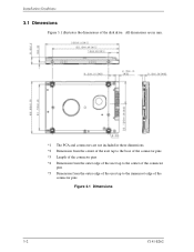
Installation Conditions 3.1 Dimensions Figure 3.1 illustrates the dimensions of the connector pins Figure 3.1 Dimensions 3-2 C141-E262 All dimensions are in mm. *1 The PCA and connectors are not included in these dimensions. *2 Dimension from the center of the user tap to the base of the connector pins *3 Length of the connector pins *4 Dimension from the outer edge of the user tap to the center of the connector pins *5 Dimension from the outer edge of the user tap to the innermost edge of the disk drive.
Installation Conditions 3.1 Dimensions Figure 3.1 illustrates the dimensions of the connector pins Figure 3.1 Dimensions 3-2 C141-E262 All dimensions are in mm. *1 The PCA and connectors are not included in these dimensions. *2 Dimension from the center of the user tap to the base of the connector pins *3 Length of the connector pins *4 Dimension from the outer edge of the user tap to the center of the connector pins *5 Dimension from the outer edge of the user tap to the innermost edge of the disk drive.
Manual/User Guide
Page 3
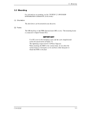
... is connected to Signal Ground (SG). C141-E262 3-3 The mounting frame is attached. 3.2 Mounting 3.2 Mounting For information on mounting, see the "FUJITSU 2.5-INCH HDD INTEGRATION GUIDANCE (C141-E144)." (1) Orientation The disk drives can be 0.49N•m (5kgf•cm). Use M3 screw for the mounting screw and the screw length should satisfy the...
... is connected to Signal Ground (SG). C141-E262 3-3 The mounting frame is attached. 3.2 Mounting 3.2 Mounting For information on mounting, see the "FUJITSU 2.5-INCH HDD INTEGRATION GUIDANCE (C141-E144)." (1) Orientation The disk drives can be 0.49N•m (5kgf•cm). Use M3 screw for the mounting screw and the screw length should satisfy the...
Manual/User Guide
Page 6
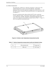
... values No. Provide air circulation in the cabinet such that the PCA side, in a cabinet refer to prevent the DE surface cover temperature from the disk drive. Measurement point Temperature 1 DE cover 60 °C max 3-6 C141-E262 To check the cooling efficiency, measure the surface cover temperatures of the ambient temperature, ... cover temperature must be considered to the ambient temperature at a point 3 cm from exceeding 60 °C. Installation Conditions (4) Ambient temperature The temperature conditions for a disk drive mounted in particular, receives sufficient cooling.
... values No. Provide air circulation in the cabinet such that the PCA side, in a cabinet refer to prevent the DE surface cover temperature from the disk drive. Measurement point Temperature 1 DE cover 60 °C max 3-6 C141-E262 To check the cooling efficiency, measure the surface cover temperatures of the ambient temperature, ... cover temperature must be considered to the ambient temperature at a point 3 cm from exceeding 60 °C. Installation Conditions (4) Ambient temperature The temperature conditions for a disk drive mounted in particular, receives sufficient cooling.
Manual/User Guide
Page 7
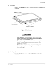
... device, disconnect the body ground (500 kΩ or greater). Damage: Do not press the cover of the disk drive. Pressing it by external magnetic fields. Ensure that the disk drive is not affected by the edges. (6) Handling cautions Please keep the following cautions, and handle the HDD under the... connection Mounting screw hole Figure 3.5 Service area Data corruption: Avoid mounting the disk drive near strong magnetic sources such as loud speakers. Do not touch the printed circuit board, but hold it too hard, the cover and the spindle motor contact, which may cause damage to the...
... device, disconnect the body ground (500 kΩ or greater). Damage: Do not press the cover of the disk drive. Pressing it by external magnetic fields. Ensure that the disk drive is not affected by the edges. (6) Handling cautions Please keep the following cautions, and handle the HDD under the... connection Mounting screw hole Figure 3.5 Service area Data corruption: Avoid mounting the disk drive near strong magnetic sources such as loud speakers. Do not touch the printed circuit board, but hold it too hard, the cover and the spindle motor contact, which may cause damage to the...
Manual/User Guide
Page 9
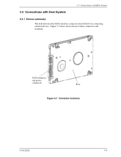
3.3 Connections with Host System 3.3 Connections with Host System 3.3.1 Device connector The disk drive has the SATA interface connectors listed below for connecting external devices. Figure 3.7 shows the locations of these connectors and terminals. SATA interface and power connectors PCA Figure 3.7 Connector locations C141-E262 3-9
3.3 Connections with Host System 3.3 Connections with Host System 3.3.1 Device connector The disk drive has the SATA interface connectors listed below for connecting external devices. Figure 3.7 shows the locations of these connectors and terminals. SATA interface and power connectors PCA Figure 3.7 Connector locations C141-E262 3-9
Manual/User Guide
Page 10
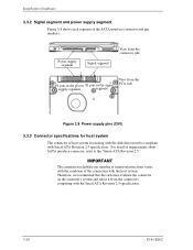
... evaluate the connector on the customer's system and select it from the PCA side Figure 3.8 Power supply pins (CN1) 3.3.3 Connector specifications for mating with the disk drive must be compliant with the host system.
... evaluate the connector on the customer's system and select it from the PCA side Figure 3.8 Power supply pins (CN1) 3.3.3 Connector specifications for mating with the disk drive must be compliant with the host system.
Manual/User Guide
Page 11
... the cable while releasing the Latch. Accordingly, be compliant with Host System 3.3.4 SATA interface cable connection The cable that connects the disk drive to the host system must be sure to connector damage and the loss of force in the connection direction once they are snugly ... of the following precaution about plugging a SATA interface cable into the SATA interface connector of the disk drive and plugging the connector into a host receptacle: When plugging together the disk drive SATA interface connector and the host receptacle or SATA interface cable connector, do not apply more than...
... the cable while releasing the Latch. Accordingly, be compliant with Host System 3.3.4 SATA interface cable connection The cable that connects the disk drive to the host system must be sure to connector damage and the loss of force in the connection direction once they are snugly ... of the following precaution about plugging a SATA interface cable into the SATA interface connector of the disk drive and plugging the connector into a host receptacle: When plugging together the disk drive SATA interface connector and the host receptacle or SATA interface cable connector, do not apply more than...


