Manual/User Guide
Page 9
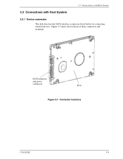
SATA interface and power connectors PCA Figure 3.7 Connector locations C141-E262 3-9 3.3 Connections with Host System 3.3 Connections with Host System 3.3.1 Device connector The disk drive has the SATA interface connectors listed below for connecting external devices. Figure 3.7 shows the locations of these connectors and terminals.
SATA interface and power connectors PCA Figure 3.7 Connector locations C141-E262 3-9 3.3 Connections with Host System 3.3 Connections with Host System 3.3.1 Device connector The disk drive has the SATA interface connectors listed below for connecting external devices. Figure 3.7 shows the locations of these connectors and terminals.
Manual/User Guide
Page 10
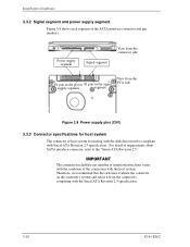
... Signal segment View from the connector side P1 pins in the power S1 pins in the signal supply segment segment View from the connectors complying with the Serial ATA Revision 2.5 specification. 3-10 C141-E262 The connection ... we recommend that the customer evaluate the connector on the customer's system and select it from the PCA side Figure 3.8 Power supply pins (CN1) 3.3.3 Connector specifications for mating with the disk drive must be compliant with the host system. For detail of the SATA interface connector and pin numbers. Installation Conditions 3.3.2 Signal...
... Signal segment View from the connector side P1 pins in the power S1 pins in the signal supply segment segment View from the connectors complying with the Serial ATA Revision 2.5 specification. 3-10 C141-E262 The connection ... we recommend that the customer evaluate the connector on the customer's system and select it from the PCA side Figure 3.8 Power supply pins (CN1) 3.3.3 Connector specifications for mating with the disk drive must be compliant with the host system. For detail of the SATA interface connector and pin numbers. Installation Conditions 3.3.2 Signal...