Manual/User Guide
Page 2
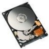
All dimensions are in mm. *1 The PCA and connectors are not included in these dimensions. *2 Dimension from the center of the user tap to the base of the connector pins *3 Length of the connector pins *4 Dimension from the outer edge of the user tap to the center of the connector pins *5 Dimension from the outer edge of the user tap to the innermost edge of the disk drive. Installation Conditions 3.1 Dimensions Figure 3.1 illustrates the dimensions of the connector pins Figure 3.1 Dimensions 3-2 C141-E262
All dimensions are in mm. *1 The PCA and connectors are not included in these dimensions. *2 Dimension from the center of the user tap to the base of the connector pins *3 Length of the connector pins *4 Dimension from the outer edge of the user tap to the center of the connector pins *5 Dimension from the outer edge of the user tap to the innermost edge of the disk drive. Installation Conditions 3.1 Dimensions Figure 3.1 illustrates the dimensions of the connector pins Figure 3.1 Dimensions 3-2 C141-E262
Manual/User Guide
Page 9
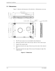
Figure 3.7 shows the locations of these connectors and terminals. SATA interface and power connectors PCA Figure 3.7 Connector locations C141-E262 3-9 3.3 Connections with Host System 3.3 Connections with Host System 3.3.1 Device connector The disk drive has the SATA interface connectors listed below for connecting external devices.
Figure 3.7 shows the locations of these connectors and terminals. SATA interface and power connectors PCA Figure 3.7 Connector locations C141-E262 3-9 3.3 Connections with Host System 3.3 Connections with Host System 3.3.1 Device connector The disk drive has the SATA interface connectors listed below for connecting external devices.
Manual/User Guide
Page 10
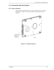
...ATA Revision 2.5." Therefore, we recommend that the customer evaluate the connector on the customer's system and select it from the PCA side Figure 3.8 Power supply pins (CN1) 3.3.3 Connector specifications for mating with the disk drive must be compliant with the Serial ATA Revision 2.5 specification. ...3-10 C141-E262 Power supply segment Signal segment View from the connector side P1 pins in the power S1 pins ...
...ATA Revision 2.5." Therefore, we recommend that the customer evaluate the connector on the customer's system and select it from the PCA side Figure 3.8 Power supply pins (CN1) 3.3.3 Connector specifications for mating with the disk drive must be compliant with the Serial ATA Revision 2.5 specification. ...3-10 C141-E262 Power supply segment Signal segment View from the connector side P1 pins in the power S1 pins ...
Manual/User Guide
Page 11
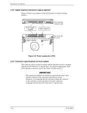
3.3 Connections with Host System 3.3.4 SATA interface cable connection The cable that connects the disk drive to the host system must be sure to connector damage and the loss of force in the connection direction once they are snugly and securely in position. C141-E262...precaution about plugging a SATA interface cable into the SATA interface connector of the disk drive and plugging the connector into a host receptacle: When plugging together the disk drive SATA interface connector and the host receptacle or SATA interface cable connector, do not apply more than 10 kgf of the Latch function...
3.3 Connections with Host System 3.3.4 SATA interface cable connection The cable that connects the disk drive to the host system must be sure to connector damage and the loss of force in the connection direction once they are snugly and securely in position. C141-E262...precaution about plugging a SATA interface cable into the SATA interface connector of the disk drive and plugging the connector into a host receptacle: When plugging together the disk drive SATA interface connector and the host receptacle or SATA interface cable connector, do not apply more than 10 kgf of the Latch function...