Manual/User Guide
Page 1
CHAPTER 3 Installation Conditions 3.1 Dimensions 3.2 Mounting 3.3 Connections with Host System This chapter gives the external dimensions, installation conditions, surface temperature conditions, cable connections, and switch settings of the hard disk drives. C141-E262 3-1
CHAPTER 3 Installation Conditions 3.1 Dimensions 3.2 Mounting 3.3 Connections with Host System This chapter gives the external dimensions, installation conditions, surface temperature conditions, cable connections, and switch settings of the hard disk drives. C141-E262 3-1
Manual/User Guide
Page 7
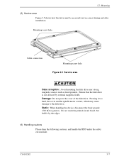
...Mounting screw hole Cable connection Mounting screw hole Figure 3.5 Service area Data corruption: Avoid mounting the disk drive near strong magnetic sources such as loud speakers. Ensure that the disk drive is not affected by the edges. (6) Handling cautions Please keep the following cautions, and handle the ... Do not press the cover of the disk drive. Static: When handling the device, disconnect the body ground (500 kΩ or greater). Pressing it by external magnetic fields. Do not touch the printed circuit board, but hold it too hard, the cover and the spindle motor contact, ...
...Mounting screw hole Cable connection Mounting screw hole Figure 3.5 Service area Data corruption: Avoid mounting the disk drive near strong magnetic sources such as loud speakers. Ensure that the disk drive is not affected by the edges. (6) Handling cautions Please keep the following cautions, and handle the ... Do not press the cover of the disk drive. Static: When handling the device, disconnect the body ground (500 kΩ or greater). Pressing it by external magnetic fields. Do not touch the printed circuit board, but hold it too hard, the cover and the spindle motor contact, ...
Manual/User Guide
Page 9
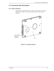
Figure 3.7 shows the locations of these connectors and terminals. SATA interface and power connectors PCA Figure 3.7 Connector locations C141-E262 3-9 3.3 Connections with Host System 3.3 Connections with Host System 3.3.1 Device connector The disk drive has the SATA interface connectors listed below for connecting external devices.
Figure 3.7 shows the locations of these connectors and terminals. SATA interface and power connectors PCA Figure 3.7 Connector locations C141-E262 3-9 3.3 Connections with Host System 3.3 Connections with Host System 3.3.1 Device connector The disk drive has the SATA interface connectors listed below for connecting external devices.
