Manual/User Guide
Page 1
CHAPTER 3 Installation Conditions 3.1 Dimensions 3.2 Mounting 3.3 Connections with Host System This chapter gives the external dimensions, installation conditions, surface temperature conditions, cable connections, and switch settings of the hard disk drives. C141-E245 3-1
CHAPTER 3 Installation Conditions 3.1 Dimensions 3.2 Mounting 3.3 Connections with Host System This chapter gives the external dimensions, installation conditions, surface temperature conditions, cable connections, and switch settings of the hard disk drives. C141-E245 3-1
Manual/User Guide
Page 2
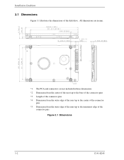
Installation Conditions 3.1 Dimensions Figure 3.1 illustrates the dimensions of the connector pins Figure 3.1 Dimensions 3-2 C141-E245 All dimensions are in mm. *1 The PCA and connectors are not included in these dimensions. *2 Dimension from the center of the user tap to the base of the connector pins *3 Length of the connector pins *4 Dimension from the outer edge of the user tap to the center of the connector pins *5 Dimension from the outer edge of the user tap to the innermost edge of the disk drive.
Installation Conditions 3.1 Dimensions Figure 3.1 illustrates the dimensions of the connector pins Figure 3.1 Dimensions 3-2 C141-E245 All dimensions are in mm. *1 The PCA and connectors are not included in these dimensions. *2 Dimension from the center of the user tap to the base of the connector pins *3 Length of the connector pins *4 Dimension from the outer edge of the user tap to the center of the connector pins *5 Dimension from the outer edge of the user tap to the innermost edge of the disk drive.
Manual/User Guide
Page 3
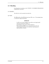
... Use M3 screw for the mounting screw and the screw length should satisfy the specification in any direction. (2) Frame The MR head bias of the HDD disk enclosure (DE) is attached. The mounting frame is connected to which the HDD is zero. C141-E245 3-3 3.2 Mounting 3.2 Mounting For information on mounting, see the "FUJITSU 2.5-INCH HDD INTEGRATION GUIDANCE (C141-E144)." (1) Orientation The disk drives...
... Use M3 screw for the mounting screw and the screw length should satisfy the specification in any direction. (2) Frame The MR head bias of the HDD disk enclosure (DE) is attached. The mounting frame is connected to which the HDD is zero. C141-E245 3-3 3.2 Mounting 3.2 Mounting For information on mounting, see the "FUJITSU 2.5-INCH HDD INTEGRATION GUIDANCE (C141-E144)." (1) Orientation The disk drives...
Manual/User Guide
Page 4
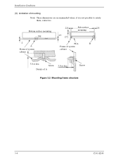
Installation Conditions (3) Limitation of A 3.0 or less Screw Figure 3.2 Mounting frame structure 3-4 C141-E245 if it is not possible to satisfy them, contact us. Bottom surface mounting DE 2 A Frame of system cabinet 2.5 2.5 2.5 Side surface 2.5 mounting PCA B Frame of system cabinet 3.0 or less Screw Details of mounting Note) These dimensions are recommended values;
Installation Conditions (3) Limitation of A 3.0 or less Screw Figure 3.2 Mounting frame structure 3-4 C141-E245 if it is not possible to satisfy them, contact us. Bottom surface mounting DE 2 A Frame of system cabinet 2.5 2.5 2.5 Side surface 2.5 mounting PCA B Frame of system cabinet 3.0 or less Screw Details of mounting Note) These dimensions are recommended values;
Manual/User Guide
Page 5
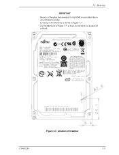
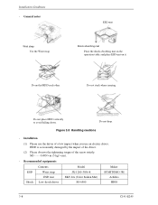
For breather hole of Figure 3.3, at least, do not allow its around φ 3 to close during mounting. Figure 3.3 Location of breather hole is shown as Figure 3.3. 3.2 Mounting IMPORTANT Because of breather hole mounted to the HDD, do not allow this to block. Locating of breather C141-E254 3-5
For breather hole of Figure 3.3, at least, do not allow its around φ 3 to close during mounting. Figure 3.3 Location of breather hole is shown as Figure 3.3. 3.2 Mounting IMPORTANT Because of breather hole mounted to the HDD, do not allow this to block. Locating of breather C141-E254 3-5
Manual/User Guide
Page 6
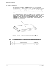
... the DE. Measurement point Temperature 1 DE cover 60 °C max 3-6 C141-E245 Figure 3.4 shows the temperature measurement point. 1 Figure 3.4 Surface cover temperature measurement points Table 3.1 Surface temperature measurement points and standard values No. Provide air circulation in the cabinet such that the PCA side, in Table 3.1. Installation Conditions (4) Ambient temperature The temperature conditions for a disk drive mounted in Section 1.4, and...
... the DE. Measurement point Temperature 1 DE cover 60 °C max 3-6 C141-E245 Figure 3.4 shows the temperature measurement point. 1 Figure 3.4 Surface cover temperature measurement points Table 3.1 Surface temperature measurement points and standard values No. Provide air circulation in the cabinet such that the PCA side, in Table 3.1. Installation Conditions (4) Ambient temperature The temperature conditions for a disk drive mounted in Section 1.4, and...
Manual/User Guide
Page 7
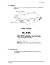
... accessed (service areas) during and after installation. Static: When handling the device, disconnect the body ground (500 kΩ or greater). Do not touch the printed circuit board, but hold it too hard, the cover and the spindle motor contact, which may cause damage to the disk drive. Damage: Do not press the cover of the disk drive. Ensure that the disk drive...
... accessed (service areas) during and after installation. Static: When handling the device, disconnect the body ground (500 kΩ or greater). Do not touch the printed circuit board, but hold it too hard, the cover and the spindle motor contact, which may cause damage to the disk drive. Damage: Do not press the cover of the disk drive. Ensure that the disk drive...
Manual/User Guide
Page 8
... not stack when carrying. Do not drop. Installation (1) Please use the driver of the screw strictly. HDD is occasionally damaged by the impact of the driver. (2) Please observe the tightening torque of a low impact when you use an electric driver. Recommended equipments ESD Shock Contents Wrist strap ESD mat Low shock driver Model JX-1200-3056-8 SKY-8A (Color...
... not stack when carrying. Do not drop. Installation (1) Please use the driver of the screw strictly. HDD is occasionally damaged by the impact of the driver. (2) Please observe the tightening torque of a low impact when you use an electric driver. Recommended equipments ESD Shock Contents Wrist strap ESD mat Low shock driver Model JX-1200-3056-8 SKY-8A (Color...
Manual/User Guide
Page 9
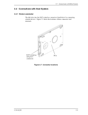
3.3 Connections with Host System 3.3 Connections with Host System 3.3.1 Device connector The disk drive has the SATA interface connectors listed below for connecting external devices. Figure 3.7 shows the locations of these connectors and terminals. SATA interface PCA and power connectors Figure 3.7 Connector locations C141-E245 3-9
3.3 Connections with Host System 3.3 Connections with Host System 3.3.1 Device connector The disk drive has the SATA interface connectors listed below for connecting external devices. Figure 3.7 shows the locations of these connectors and terminals. SATA interface PCA and power connectors Figure 3.7 Connector locations C141-E245 3-9
Manual/User Guide
Page 10
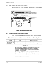
... condition of the SATA interface connector and pin numbers. Table 3.2 The recommended connector specifications for the host system Segment SATA interface and power supply Name Host receptacle Model (Manufacturer) 67492-0220 (Molex) or compatibles IMPORTANT The above connector specifications for the host system indicate only that the customer evaluate the connecter on the customer's system and select it from the PCA side Figure 3.8 Power supply pins (CN1) 3.3.3 Connector specifications for host system...
... condition of the SATA interface connector and pin numbers. Table 3.2 The recommended connector specifications for the host system Segment SATA interface and power supply Name Host receptacle Model (Manufacturer) 67492-0220 (Molex) or compatibles IMPORTANT The above connector specifications for the host system indicate only that the customer evaluate the connecter on the customer's system and select it from the PCA side Figure 3.8 Power supply pins (CN1) 3.3.3 Connector specifications for host system...
Manual/User Guide
Page 11
... with the Serial ATA 1.0a specification. 3.3.5 Note about SATA interface cable connection Take note of the following precaution about plugging a SATA interface cable into the SATA interface connector of the disk drive and plugging the connector into a host receptacle: When plugging together the disk drive SATA interface connector and the host receptacle or SATA interface cable connector, do not apply more than 10 kgf of force in the connection direction once they are snugly and securely in...
... with the Serial ATA 1.0a specification. 3.3.5 Note about SATA interface cable connection Take note of the following precaution about plugging a SATA interface cable into the SATA interface connector of the disk drive and plugging the connector into a host receptacle: When plugging together the disk drive SATA interface connector and the host receptacle or SATA interface cable connector, do not apply more than 10 kgf of force in the connection direction once they are snugly and securely in...


