Manual/User Guide
Page 1
CHAPTER 3 Installation Conditions 3.1 Dimensions 3.2 Mounting 3.3 Connections with Host System This chapter gives the external dimensions, installation conditions, surface temperature conditions, cable connections, and switch settings of the hard disk drives. C141-E245 3-1
CHAPTER 3 Installation Conditions 3.1 Dimensions 3.2 Mounting 3.3 Connections with Host System This chapter gives the external dimensions, installation conditions, surface temperature conditions, cable connections, and switch settings of the hard disk drives. C141-E245 3-1
Manual/User Guide
Page 2
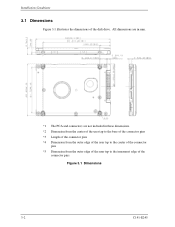
All dimensions are in mm. *1 The PCA and connectors are not included in these dimensions. *2 Dimension from the center of the user tap to the base of the connector pins *3 Length of the connector pins *4 Dimension from the outer edge of the user tap to the center of the connector pins *5 Dimension from the outer edge of the user tap to the innermost edge of the disk drive. Installation Conditions 3.1 Dimensions Figure 3.1 illustrates the dimensions of the connector pins Figure 3.1 Dimensions 3-2 C141-E245
All dimensions are in mm. *1 The PCA and connectors are not included in these dimensions. *2 Dimension from the center of the user tap to the base of the connector pins *3 Length of the connector pins *4 Dimension from the outer edge of the user tap to the center of the connector pins *5 Dimension from the outer edge of the user tap to the innermost edge of the disk drive. Installation Conditions 3.1 Dimensions Figure 3.1 illustrates the dimensions of the connector pins Figure 3.1 Dimensions 3-2 C141-E245
Manual/User Guide
Page 3
... (cover and base) other than parts to Signal Ground (SG). C141-E245 3-3 3.2 Mounting 3.2 Mounting For information on mounting, see the "FUJITSU 2.5-INCH HDD INTEGRATION GUIDANCE (C141-E144)." (1) Orientation The disk drives can be 0.49N•m (5kgf•cm). The tightening torque must be mounted in Figure 3.2. The mounting frame is connected to...
... (cover and base) other than parts to Signal Ground (SG). C141-E245 3-3 3.2 Mounting 3.2 Mounting For information on mounting, see the "FUJITSU 2.5-INCH HDD INTEGRATION GUIDANCE (C141-E144)." (1) Orientation The disk drives can be 0.49N•m (5kgf•cm). The tightening torque must be mounted in Figure 3.2. The mounting frame is connected to...
Manual/User Guide
Page 4
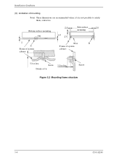
if it is not possible to satisfy them, contact us. Bottom surface mounting DE 2 A Frame of system cabinet 2.5 2.5 2.5 Side surface 2.5 mounting PCA B Frame of system cabinet 3.0 or less Screw Details of mounting Note) These dimensions are recommended values; Installation Conditions (3) Limitation of A 3.0 or less Screw Figure 3.2 Mounting frame structure 3-4 C141-E245
if it is not possible to satisfy them, contact us. Bottom surface mounting DE 2 A Frame of system cabinet 2.5 2.5 2.5 Side surface 2.5 mounting PCA B Frame of system cabinet 3.0 or less Screw Details of mounting Note) These dimensions are recommended values; Installation Conditions (3) Limitation of A 3.0 or less Screw Figure 3.2 Mounting frame structure 3-4 C141-E245
Manual/User Guide
Page 5
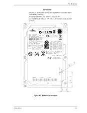
For breather hole of Figure 3.3, at least, do not allow its around φ 3 to close during mounting. Figure 3.3 Location of breather hole is shown as Figure 3.3. 3.2 Mounting IMPORTANT Because of breather hole mounted to the HDD, do not allow this to block. Locating of breather C141-E254 3-5
For breather hole of Figure 3.3, at least, do not allow its around φ 3 to close during mounting. Figure 3.3 Location of breather hole is shown as Figure 3.3. 3.2 Mounting IMPORTANT Because of breather hole mounted to the HDD, do not allow this to block. Locating of breather C141-E254 3-5
Manual/User Guide
Page 6
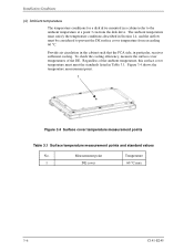
Regardless of the DE. Installation Conditions (4) Ambient temperature The temperature conditions for a disk drive mounted in particular, receives sufficient cooling. To check the cooling efficiency, measure the surface cover temperatures of the ambient temperature, this ...No. Provide air circulation in the cabinet such that the PCA side, in a cabinet refer to prevent the DE surface cover temperature from the disk drive. Measurement point Temperature 1 DE cover 60 °C max 3-6 C141-E245 The ambient temperature must be considered to the ambient temperature at a point ...
Regardless of the DE. Installation Conditions (4) Ambient temperature The temperature conditions for a disk drive mounted in particular, receives sufficient cooling. To check the cooling efficiency, measure the surface cover temperatures of the ambient temperature, this ...No. Provide air circulation in the cabinet such that the PCA side, in a cabinet refer to prevent the DE surface cover temperature from the disk drive. Measurement point Temperature 1 DE cover 60 °C max 3-6 C141-E245 The ambient temperature must be considered to the ambient temperature at a point ...
Manual/User Guide
Page 7
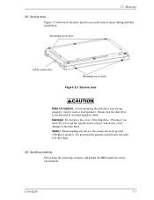
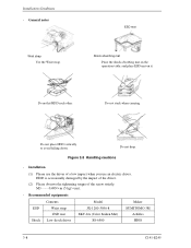
...Damage: Do not press the cover of the disk drive. C141-E245 3-7 3.2 Mounting (5) Service area Figure 3.5 shows how the drive must be accessed (service areas) during and after installation. Do not touch the printed circuit board, but hold it too hard, the cover and the spindle motor contact, which ...may cause damage to the disk drive. Pressing it by external magnetic fields. Ensure that the disk drive is not affected by the edges. (6) Handling cautions Please keep the...
...Damage: Do not press the cover of the disk drive. C141-E245 3-7 3.2 Mounting (5) Service area Figure 3.5 shows how the drive must be accessed (service areas) during and after installation. Do not touch the printed circuit board, but hold it too hard, the cover and the spindle motor contact, which ...may cause damage to the disk drive. Pressing it by external magnetic fields. Ensure that the disk drive is not affected by the edges. (6) Handling cautions Please keep the...
Manual/User Guide
Page 8
Installation Conditions - Do not stack when carrying. Installation (1) Please use an electric driver. Do not place HDD vertically to avoid falling down. Recommended equipments ESD Shock Contents Wrist strap ESD mat Low shock driver Model JX-1200-3056-8 SKY-8A (Color Seiden Mat) SS-6500 Maker SUMITOMO 3M Achilles HIOS 3-8 C141-E245 Do not drop. ESD mat Shock absorbing mat Place the shock absorbing mat on the operation table, and place ESD mat on it. General notes Wrist strap Use the Wrist strap. M3 0.49N • m (5 kgf • cm). - HDD is occasionally ...
Installation Conditions - Do not stack when carrying. Installation (1) Please use an electric driver. Do not place HDD vertically to avoid falling down. Recommended equipments ESD Shock Contents Wrist strap ESD mat Low shock driver Model JX-1200-3056-8 SKY-8A (Color Seiden Mat) SS-6500 Maker SUMITOMO 3M Achilles HIOS 3-8 C141-E245 Do not drop. ESD mat Shock absorbing mat Place the shock absorbing mat on the operation table, and place ESD mat on it. General notes Wrist strap Use the Wrist strap. M3 0.49N • m (5 kgf • cm). - HDD is occasionally ...
Manual/User Guide
Page 9
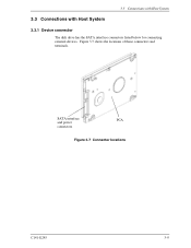
SATA interface PCA and power connectors Figure 3.7 Connector locations C141-E245 3-9 3.3 Connections with Host System 3.3 Connections with Host System 3.3.1 Device connector The disk drive has the SATA interface connectors listed below for connecting external devices. Figure 3.7 shows the locations of these connectors and terminals.
SATA interface PCA and power connectors Figure 3.7 Connector locations C141-E245 3-9 3.3 Connections with Host System 3.3 Connections with Host System 3.3.1 Device connector The disk drive has the SATA interface connectors listed below for connecting external devices. Figure 3.7 shows the locations of these connectors and terminals.
Manual/User Guide
Page 10
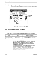
Installation Conditions 3.3.2 Signal segment and power supply segment Figure 3.8 shows each segment of the connection with the host system. The connection reliability per number of insertion/extractions varies with the SATA interface connecter is not guaranteed. Accordingly, the number connecter insertion/extractions including hot plugging is confirmed. Power supply segment Signal segment View from the connector side S1 pins in the signal P1 pins in the power segment supply segment View from the several choices including its mating with the condition of the SATA interface...
Installation Conditions 3.3.2 Signal segment and power supply segment Figure 3.8 shows each segment of the connection with the host system. The connection reliability per number of insertion/extractions varies with the SATA interface connecter is not guaranteed. Accordingly, the number connecter insertion/extractions including hot plugging is confirmed. Power supply segment Signal segment View from the connector side S1 pins in the signal P1 pins in the power segment supply segment View from the several choices including its mating with the condition of the SATA interface...
Manual/User Guide
Page 11
C141-E245 3-11 3.3 Connections with Host System 3.3.4 SATA interface cable connection The cable that connects the disk drive to the host system must be compliant with the Serial ATA 1.0a specification. 3.3.5 Note about SATA interface cable connection Take note of the ...following precaution about plugging a SATA interface cable into the SATA interface connector of the disk drive and plugging the connector into a host receptacle: When plugging together the disk drive SATA interface connector and the host receptacle or SATA interface cable connector, do not apply more than 10 kgf...
C141-E245 3-11 3.3 Connections with Host System 3.3.4 SATA interface cable connection The cable that connects the disk drive to the host system must be compliant with the Serial ATA 1.0a specification. 3.3.5 Note about SATA interface cable connection Take note of the ...following precaution about plugging a SATA interface cable into the SATA interface connector of the disk drive and plugging the connector into a host receptacle: When plugging together the disk drive SATA interface connector and the host receptacle or SATA interface cable connector, do not apply more than 10 kgf...

Manual/User Guide
Page 12
This page is intentionally left blank.
This page is intentionally left blank.