Manual/User Guide
Page 5
... procedure correctly. This alert signal also indicates that could result in this manual, disk drives may occur if the user does not perform the procedure correctly. Preface This manual describes the MHV2120AT, MHV2100AT, MHV2080AT, MHV2060AT, MHV2040AT 2.5-inch hard disk drive with the ATA interface. This manual assumes that is a registered trademark of IBM (International...
... procedure correctly. This alert signal also indicates that could result in this manual, disk drives may occur if the user does not perform the procedure correctly. Preface This manual describes the MHV2120AT, MHV2100AT, MHV2080AT, MHV2060AT, MHV2040AT 2.5-inch hard disk drive with the ATA interface. This manual assumes that is a registered trademark of IBM (International...
Manual/User Guide
Page 6
...the Product Manual (C141-E218). Operating Environment This product is designed to show where the alert message begins and ends. ii C141-F072 Fujitsu is not liable for users to defects that involve adjustment, repair, or replacement. Preface In the text, the alert signal is centered... by user misoperation or mishandling, inappropriate operating environments, defects in the power supply or cable, problems of the host system, or other disk drive defects, such as those caused by the indented message. The following is an example: (Example) Don't install or remove a PCA or connect...
...the Product Manual (C141-E218). Operating Environment This product is designed to show where the alert message begins and ends. ii C141-F072 Fujitsu is not liable for users to defects that involve adjustment, repair, or replacement. Preface In the text, the alert signal is centered... by user misoperation or mishandling, inappropriate operating environments, defects in the power supply or cable, problems of the host system, or other disk drive defects, such as those caused by the indented message. The following is an example: (Example) Don't install or remove a PCA or connect...
Manual/User Guide
Page 7
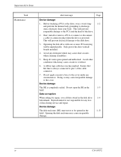
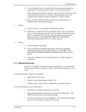
Don't install or remove a PCA or connect or disconnect 1-2 a cable or connector plug when the drive is cleaned. This may give you an electric shock. 2. Important Alert Items Important Alert Messages The important alert messages in the unit during operation.... Also, damage to the predate or other property, may occur if the user does not perform the procedure correctly. Avoid dangerous detergent when the disk drive is powered. The following manual also contains notes on safety precautions: Task Maintenance A hazardous situation could result in minor or moderate personal injury if the...
Don't install or remove a PCA or connect or disconnect 1-2 a cable or connector plug when the drive is cleaned. This may give you an electric shock. 2. Important Alert Items Important Alert Messages The important alert messages in the unit during operation.... Also, damage to the predate or other property, may occur if the user does not perform the procedure correctly. Avoid dangerous detergent when the disk drive is powered. The following manual also contains notes on safety precautions: Task Maintenance A hazardous situation could result in minor or moderate personal injury if the...
Manual/User Guide
Page 8
... a PCA or connect or disconnect a cable or connector plug when the drive is not responsible for repair, save all boards installed. 4. Keep all vents open the DE in the disk drive 1-4 beforehand. Doing so may cause irreparable damage. Data corruption When asking ... unblocked. Device damage The disk enclosure (DE) must never to overheat. 6. Before touching a PCA or the drive, wear a wrist strap 1-2 and perform the human body grounding to the disk drive. 3. Fujitsu Limited is powered. Important Alert Items Task Maintenance Alert message Page Device damage 1.
... a PCA or connect or disconnect a cable or connector plug when the drive is not responsible for repair, save all boards installed. 4. Keep all vents open the DE in the disk drive 1-4 beforehand. Doing so may cause irreparable damage. Data corruption When asking ... unblocked. Device damage The disk enclosure (DE) must never to overheat. 6. Before touching a PCA or the drive, wear a wrist strap 1-2 and perform the human body grounding to the disk drive. 3. Fujitsu Limited is powered. Important Alert Items Task Maintenance Alert message Page Device damage 1.
Manual/User Guide
Page 9
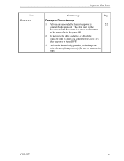
Perform the human body grounding to discharge any removal after the power is 2-2 completely disconnected. C141-F072 v Do not move the drive and attach or detach the connector until it comes to wear a wrist strap). The cable must not be disconnected and the screws that attach the drive must not be removed with the power ON. 2. Task Maintenance Important Alert Items Alert message Page Damage or Device damage 1. Perform any static electricity from your body (Be sure to a complete stop (about 30 s after the system power is turned OFF). 3.
Perform the human body grounding to discharge any removal after the power is 2-2 completely disconnected. C141-F072 v Do not move the drive and attach or detach the connector until it comes to wear a wrist strap). The cable must not be disconnected and the screws that attach the drive must not be removed with the power ON. 2. Task Maintenance Important Alert Items Alert message Page Damage or Device damage 1. Perform any static electricity from your body (Be sure to a complete stop (about 30 s after the system power is turned OFF). 3.
Manual/User Guide
Page 11
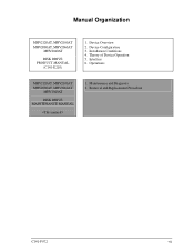
Device Overview 2. Removal and Replacement Procedure C141-F072 vii Operations MHV2120AT, MHV2100AT MHV2080AT, MHV2060AT MHV2040AT DISK DRIVE MAINTENANCE MANUAL 1. Device Configuration 3. Theory of Device Operation 5. Maintenance and Diagnosis 2. Manual Organization MHV2120AT, MHV2100AT MHV2080AT, MHV2060AT MHV2040AT DISK DRIVE PRODUCT MANUAL (C141-E218) 1. Interface 6. Installation Conditions 4.
Device Overview 2. Removal and Replacement Procedure C141-F072 vii Operations MHV2120AT, MHV2100AT MHV2080AT, MHV2060AT MHV2040AT DISK DRIVE MAINTENANCE MANUAL 1. Device Configuration 3. Theory of Device Operation 5. Maintenance and Diagnosis 2. Manual Organization MHV2120AT, MHV2100AT MHV2080AT, MHV2060AT MHV2040AT DISK DRIVE PRODUCT MANUAL (C141-E218) 1. Interface 6. Installation Conditions 4.
Manual/User Guide
Page 13
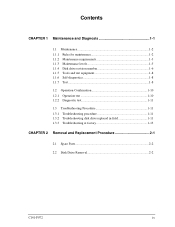
... 1 Maintenance and Diagnosis 1-1 1.1 Maintenance 1-2 1.1.1 1.1.2 1.1.3 1.1.4 1.1.5 1.1.6 1.1.7 Rules for maintenance 1-2 Maintenance requirements 1-3 Maintenance levels 1-5 Disk drive revision number 1-6 Tools and test equipment 1-8 Self-diagnostics 1-8 Test...1-8 1.2 Operation Confirmation 1-10 1.2.1 Operation test 1-10 1.2.2 Diagnostic test 1-11 1.3 Troubleshooting Procedure 1-11 1.3.1 Troubleshooting procedure 1-11 1.3.2 Troubleshooting disk drive replaced in field 1-11 1.3.3 Troubleshooting at factory 1-13 CHAPTER 2 Removal and Replacement...
... 1 Maintenance and Diagnosis 1-1 1.1 Maintenance 1-2 1.1.1 1.1.2 1.1.3 1.1.4 1.1.5 1.1.6 1.1.7 Rules for maintenance 1-2 Maintenance requirements 1-3 Maintenance levels 1-5 Disk drive revision number 1-6 Tools and test equipment 1-8 Self-diagnostics 1-8 Test...1-8 1.2 Operation Confirmation 1-10 1.2.1 Operation test 1-10 1.2.2 Diagnostic test 1-11 1.3 Troubleshooting Procedure 1-11 1.3.1 Troubleshooting procedure 1-11 1.3.2 Troubleshooting disk drive replaced in field 1-11 1.3.3 Troubleshooting at factory 1-13 CHAPTER 2 Removal and Replacement...
Manual/User Guide
Page 14
Contents Illustrations Figures Tables Figure 1.1 Disk drive revision number label 1-6 Figure 1.2 Display of disk drive revision number 1-7 Figure 1.3 Test flowchart 1-9 Table 1.1 Table 1.2 Table 1.3 Status register contents 1-10 Disposition for error register contents 1-10 System level and field troubleshooting 1-12 Table 2.1 Model and parts numbers 2-2 x C141-F072
Contents Illustrations Figures Tables Figure 1.1 Disk drive revision number label 1-6 Figure 1.2 Display of disk drive revision number 1-7 Figure 1.3 Test flowchart 1-9 Table 1.1 Table 1.2 Table 1.3 Status register contents 1-10 Disposition for error register contents 1-10 System level and field troubleshooting 1-12 Table 2.1 Model and parts numbers 2-2 x C141-F072

Manual/User Guide
Page 15
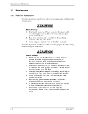
... for each maintenance level • Recommended procedure for regular maintenance and troubleshooting • Display of maintenance level (field and factory) • Display of the disk drive. The following are explained: • Rules for troubleshooting and fault diagnosis C141-F072 1-1
... for each maintenance level • Recommended procedure for regular maintenance and troubleshooting • Display of maintenance level (field and factory) • Display of the disk drive. The following are explained: • Rules for troubleshooting and fault diagnosis C141-F072 1-1
Manual/User Guide
Page 16
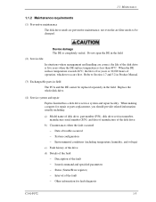
... when cleaning assemblies. 5. Don't install or remove a PCA or connect or disconnect a cable or connector plug when the drive is cleaned. This will prevent electrical damage to discharge static electricity from mechanical assemblies in the unit during operation. Do not... connector. 7. Keep all boards installed. 4. Doing so may give you an electric shock. 2. Avoid dangerous detergent when the disk drive is powered. Device damage 1. Avoid any circumstances. Maintenance and Diagnosis 1.1 Maintenance 1.1.1 Rules for maintenance The following cautions must be observed...
... when cleaning assemblies. 5. Don't install or remove a PCA or connect or disconnect a cable or connector plug when the drive is cleaned. This will prevent electrical damage to discharge static electricity from mechanical assemblies in the unit during operation. Do not... connector. 7. Keep all boards installed. 4. Doing so may give you an electric shock. 2. Avoid dangerous detergent when the disk drive is powered. Device damage 1. Avoid any circumstances. Maintenance and Diagnosis 1.1 Maintenance 1.1.1 Rules for maintenance The following cautions must be observed...
Manual/User Guide
Page 17
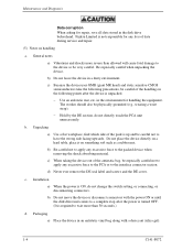
Replace the whole disk drive. (4) Service system and repair Fujitsu Limited has a disk drive service system and repair facility. When the DE surface temperature exceeds 48°C, the life is five years or 20,000 hours of the disk drive is five years when the DE...situations where management and handling are correct, the life of operation, whichever occurs first. 1.1 Maintenance 1.1.2 Maintenance requirements (1) Preventive maintenance The disk drive needs no preventive maintenance, not even the air filter needs to Section 1.7 and 3.2 in Product Manual. (3) Exchangeable parts in field The ...
Replace the whole disk drive. (4) Service system and repair Fujitsu Limited has a disk drive service system and repair facility. When the DE surface temperature exceeds 48°C, the life is five years or 20,000 hours of the disk drive is five years when the DE...situations where management and handling are correct, the life of operation, whichever occurs first. 1.1 Maintenance 1.1.2 Maintenance requirements (1) Preventive maintenance The disk drive needs no preventive maintenance, not even the air filter needs to Section 1.7 and 3.2 in Product Manual. (3) Exchangeable parts in field The ...
Manual/User Guide
Page 18
...to a complete stop after the device is ON, do not directly touch the PCA unit unnecessarily. in the disk drive beforehand. Do not place the device directly on a hard table, place it on handling a. c. Maintenance and Diagnosis Data corruption When asking for repair, save all data ...power is unpacked. − Use an antistatic mat, etc. d) Never ever remove the DE seal label and screws and the DE cover. Fujitsu Limited is not responsible for handling the equipment. c) Because the device uses GMR (giant MR head) and static sensitive CMOS semiconductors take the following...
...to a complete stop after the device is ON, do not directly touch the PCA unit unnecessarily. in the disk drive beforehand. Do not place the device directly on a hard table, place it on handling a. c. Maintenance and Diagnosis Data corruption When asking for repair, save all data ...power is unpacked. − Use an antistatic mat, etc. d) Never ever remove the DE seal label and screws and the DE cover. Fujitsu Limited is not responsible for handling the equipment. c) Because the device uses GMR (giant MR head) and static sensitive CMOS semiconductors take the following...
Manual/User Guide
Page 19
...; This includes maintenance training and assisting other OEM traders. Storage a) Store in Section 1.4 of the MHV2120AT, MHV2100AT, MHV2080AT, MHV2060AT, MHV2040AT Disk Drives Product Manual. b) Take care that will replace the drive. (2) Factory maintenance (parts replacement) • Only Fujitsu can perform maintenance at this type of box, adequately protect the PCA surface and interface connector...
...; This includes maintenance training and assisting other OEM traders. Storage a) Store in Section 1.4 of the MHV2120AT, MHV2100AT, MHV2080AT, MHV2060AT, MHV2040AT Disk Drives Product Manual. b) Take care that will replace the drive. (2) Factory maintenance (parts replacement) • Only Fujitsu can perform maintenance at this type of box, adequately protect the PCA surface and interface connector...
Manual/User Guide
Page 20
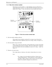
... number is stuck on the DE and marked on the revision number label. Disk drive revision number Firmware code/revision Figure 1.1 Disk drive revision number label (1) Revision number marking at delivery The machine revision number is indicated by crossing out up to ...revision number level should be changed as described above. 1-6 C141-F072 Note: For a change of revision number after delivery, Fujitsu issues a "Change Request/Notice" and the disk drive revision number after the change is replaced in the relevant alphabetic character row using = marks (see Figure 1.2). (3) Firmware code...
... number is stuck on the DE and marked on the revision number label. Disk drive revision number Firmware code/revision Figure 1.1 Disk drive revision number label (1) Revision number marking at delivery The machine revision number is indicated by crossing out up to ...revision number level should be changed as described above. 1-6 C141-F072 Note: For a change of revision number after delivery, Fujitsu issues a "Change Request/Notice" and the disk drive revision number after the change is replaced in the relevant alphabetic character row using = marks (see Figure 1.2). (3) Firmware code...
Manual/User Guide
Page 21
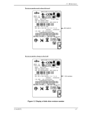
Revision number mark when delivered 1.1 Maintenance A2 revision Revision number change in the field A3 revision Figure 1.2 Display of disk drive revision number C141-F072 1-7
Revision number mark when delivered 1.1 Maintenance A2 revision Revision number change in the field A3 revision Figure 1.2 Display of disk drive revision number C141-F072 1-7
Manual/User Guide
Page 22
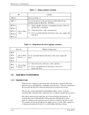
...Tools and test equipment At the field maintenance level, only ordinary hand tools are beyond the scope of an isolated disk drive can be checked. • Initial self-diagnostics • SMART command (SMART Execute Off-Line Immediate command) 1.1.7 Test The disk... can be divided into the following self-diagnostics. These self-diagnostics allow normal basic operation of this manual. 1.1.6 Self-diagnostics The disk drive has the following three levels. • Operating test (See Subsection 1.2.1, "Operating test.") • Diagnostic test (See Subsection 1.2.2, "Diagnostic test.") Figure 1.3...
...Tools and test equipment At the field maintenance level, only ordinary hand tools are beyond the scope of an isolated disk drive can be checked. • Initial self-diagnostics • SMART command (SMART Execute Off-Line Immediate command) 1.1.7 Test The disk... can be divided into the following self-diagnostics. These self-diagnostics allow normal basic operation of this manual. 1.1.6 Self-diagnostics The disk drive has the following three levels. • Operating test (See Subsection 1.2.1, "Operating test.") • Diagnostic test (See Subsection 1.2.2, "Diagnostic test.") Figure 1.3...
Manual/User Guide
Page 23
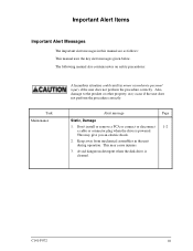
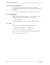
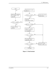
Yes Diagnostic test with the host computer or test equipment No Test acceptable? Yes Disk drive replacement or repair No Disk drive normal? Yes Test using voltage or temperature stress Test acceptable? Yes No failure No Disk drive failure analysis (Table 1.2) Figure 1.3 Test flowchart C141-F072 1-9 1.1 Maintenance Start Yes Check the host system (Table 1.1) Operation test with the host computer or test equipment Analyze the system related failure No Test acceptable? Yes Continue with the operation No System normal?
Yes Diagnostic test with the host computer or test equipment No Test acceptable? Yes Disk drive replacement or repair No Disk drive normal? Yes Test using voltage or temperature stress Test acceptable? Yes No failure No Disk drive failure analysis (Table 1.2) Figure 1.3 Test flowchart C141-F072 1-9 1.1 Maintenance Start Yes Check the host system (Table 1.1) Operation test with the host computer or test equipment Analyze the system related failure No Test acceptable? Yes Continue with the operation No System normal?
Manual/User Guide
Page 24
...no timing and mechanical reserves, or relationship with other bits are normal, in particular processes. drive. The host is notified of the error that the disk drive is the cause, replace the disk drive. To ascertain the cause of its result. Maintenance and Diagnosis Table 1.1 Status register contents Bit... Contents BIT0=1 BIT1, 2 BIT3=1 BIT4=1 BIT5=1 BIT6=0 BIT7=1 Any of these If it is concluded that the disk drive is the cause, replace the bits are "1". Any of these bits. (Normal) (1) Check whether vibration is transmitted because of the way the disk...
...no timing and mechanical reserves, or relationship with other bits are normal, in particular processes. drive. The host is notified of the error that the disk drive is the cause, replace the disk drive. To ascertain the cause of its result. Maintenance and Diagnosis Table 1.1 Status register contents Bit... Contents BIT0=1 BIT1, 2 BIT3=1 BIT4=1 BIT5=1 BIT6=0 BIT7=1 Any of these If it is concluded that the disk drive is the cause, replace the bits are "1". Any of these bits. (Normal) (1) Check whether vibration is transmitted because of the way the disk...
Manual/User Guide
Page 25
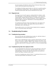
...the same fault as the one that caused the failure. The procedures used to separate a confirmed disk drive failure to a disk drive subassembly or to check the disk drive performance. Usually, troubleshooting is necessary only when a cause of this manual. 1.3 Troubleshooting Procedure 1.3.1 Troubleshooting... elsewhere in the test at this level. The engineer then isolates the failure to the disk drive or system. A test of this level usually includes a specific disk drive function or concentrated execution of a group of this level, accurately reproduce the condition that was ...
...the same fault as the one that caused the failure. The procedures used to separate a confirmed disk drive failure to a disk drive subassembly or to check the disk drive performance. Usually, troubleshooting is necessary only when a cause of this manual. 1.3 Troubleshooting Procedure 1.3.1 Troubleshooting... elsewhere in the test at this level. The engineer then isolates the failure to the disk drive or system. A test of this level usually includes a specific disk drive function or concentrated execution of a group of this level, accurately reproduce the condition that was ...
Manual/User Guide
Page 26
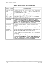
...interface cable connection Switch setting System cable System diagnostic test Intermittent or indefinite error Confirm that the DC power voltage is less than 100 mV peak to peak and 200 mV peak to peak respectively. Check the AC voltage level at the power supply section and ...recheck the DC voltage level at the disk drive, power supply section, and control unit. If possible, replace the disk drive. When measured at pins 41, 42 and 43 of the MHV2120AT, MHV2100AT, MHV2080AT, MHV2060AT, MHV2040AT Disk Drives Product Manual for normal operation with the system. 1-12 ...
...interface cable connection Switch setting System cable System diagnostic test Intermittent or indefinite error Confirm that the DC power voltage is less than 100 mV peak to peak and 200 mV peak to peak respectively. Check the AC voltage level at the power supply section and ...recheck the DC voltage level at the disk drive, power supply section, and control unit. If possible, replace the disk drive. When measured at pins 41, 42 and 43 of the MHV2120AT, MHV2100AT, MHV2080AT, MHV2060AT, MHV2040AT Disk Drives Product Manual for normal operation with the system. 1-12 ...

