Maintenance Manual
Page 2
... such as "mission-critical" use of This Manual This manual contains important information for using the product. FUJITSU DISCLAIMS ALL WARRANTIES REGARDING THE INFORMATION CONTAINED HEREIN, WHETHER EXPRESSED, IMPLIED, OR STATUTORY. Customers considering the use ). This product is not intended for special uses (atomic controls, aeronautic or space systems, mass transport controls, medical devices for any damage caused by any error or omission contained in this...
... such as "mission-critical" use of This Manual This manual contains important information for using the product. FUJITSU DISCLAIMS ALL WARRANTIES REGARDING THE INFORMATION CONTAINED HEREIN, WHETHER EXPRESSED, IMPLIED, OR STATUTORY. Customers considering the use ). This product is not intended for special uses (atomic controls, aeronautic or space systems, mass transport controls, medical devices for any damage caused by any error or omission contained in this...
Maintenance Manual
Page 5
... computer systems. This manual consists of Manual CHAPTER 1 Maintenance and Diagnosis This chapter explains MHV2080AS, MHV2060AS, MHV2040AS maintenance requirements, operation verification, and troubleshooting. C141-F073 i IBM PC-AT is compatible with a built-in controller that users have a basic knowledge of hard disk drives and their application in this manual, disk drives may occur if the user does not perform the procedure correctly. This manual explains, in minor...
... computer systems. This manual consists of Manual CHAPTER 1 Maintenance and Diagnosis This chapter explains MHV2080AS, MHV2060AS, MHV2040AS maintenance requirements, operation verification, and troubleshooting. C141-F073 i IBM PC-AT is compatible with a built-in controller that users have a basic knowledge of hard disk drives and their application in this manual, disk drives may occur if the user does not perform the procedure correctly. This manual explains, in minor...
Maintenance Manual
Page 6
..., repair, or replacement. This may have regarding the operating environment of use, refer to understand, opinions from readers are also listed in the sheet. Operating Environment This product is not liable for users to the Product Manual (C141-E221). Attention Please forward any other causes outside the disk drive. The following is an example: (Example) Don't install or remove a PCA or connect or disconnect a cable or connector...
..., repair, or replacement. This may have regarding the operating environment of use, refer to understand, opinions from readers are also listed in the sheet. Operating Environment This product is not liable for users to the Product Manual (C141-E221). Attention Please forward any other causes outside the disk drive. The following is an example: (Example) Don't install or remove a PCA or connect or disconnect a cable or connector...
Maintenance Manual
Page 7
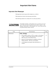
... if the user does not perform the procedure correctly. Don't install or remove a PCA or connect or disconnect 1-2 a cable or connector plug when the drive is cleaned. This may cause injuries. 3. Avoid dangerous detergent when the disk drive is powered. Important Alert Items Important Alert Messages The important alert messages in the unit during operation. C141-F073 iii The following manual also contains...
... if the user does not perform the procedure correctly. Don't install or remove a PCA or connect or disconnect 1-2 a cable or connector plug when the drive is cleaned. This may cause injuries. 3. Avoid dangerous detergent when the disk drive is powered. Important Alert Items Important Alert Messages The important alert messages in the unit during operation. C141-F073 iii The following manual also contains...
Maintenance Manual
Page 8
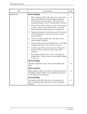
... and the head of data during service and repair. Device damage The DE is powered. iv C141-F073 Don't install or remove a PCA or connect or disconnect a cable or connector plug when the drive is completely sealed. Ensure that this line is not responsible for repair, save all boards installed. 4. This will prevent irreparable damage to the disk drive. 3. Do not open opened in the disk drive 1-4 beforehand. Only power the drive with...
... and the head of data during service and repair. Device damage The DE is powered. iv C141-F073 Don't install or remove a PCA or connect or disconnect a cable or connector plug when the drive is completely sealed. Ensure that this line is not responsible for repair, save all boards installed. 4. This will prevent irreparable damage to the disk drive. 3. Do not open opened in the disk drive 1-4 beforehand. Only power the drive with...
Maintenance Manual
Page 11
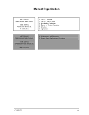
Maintenance and Diagnosis 2. Installation Conditions 4. Theory of Device Operation 5. Device Overview 2. Manual Organization MHV2080AS MHV2060AS, MHV2040AS DISK DRIVE PRODUCT MANUAL (C141-E221) 1. Operations MHV2080AS MHV2060AS, MHV2040AS DISK DRIVE MAINTENANCE MANUAL 1. Interface 6. Device Configuration 3. Removal and Replacement Procedure C141-F073 vii
Maintenance and Diagnosis 2. Installation Conditions 4. Theory of Device Operation 5. Device Overview 2. Manual Organization MHV2080AS MHV2060AS, MHV2040AS DISK DRIVE PRODUCT MANUAL (C141-E221) 1. Operations MHV2080AS MHV2060AS, MHV2040AS DISK DRIVE MAINTENANCE MANUAL 1. Interface 6. Device Configuration 3. Removal and Replacement Procedure C141-F073 vii
Maintenance Manual
Page 13
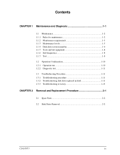
... 1-2 1.1.1 1.1.2 1.1.3 1.1.4 1.1.5 1.1.6 1.1.7 Rules for maintenance 1-2 Maintenance requirements 1-3 Maintenance levels 1-5 Disk drive revision number 1-6 Tools and test equipment 1-8 Self-diagnostics 1-8 Test...1-8 1.2 Operation Confirmation 1-10 1.2.1 Operation test 1-10 1.2.2 Diagnostic test 1-11 1.3 Troubleshooting Procedure 1-11 1.3.1 Troubleshooting procedure 1-11 1.3.2 Troubleshooting disk drive replaced in field 1-11 1.3.3 Troubleshooting at factory 1-13 CHAPTER 2 Removal and Replacement Procedure 2-1 2.1 Spare Parts 2-2 2.2 Disk Drive Removal 2-2 C141-F073 ix
... 1-2 1.1.1 1.1.2 1.1.3 1.1.4 1.1.5 1.1.6 1.1.7 Rules for maintenance 1-2 Maintenance requirements 1-3 Maintenance levels 1-5 Disk drive revision number 1-6 Tools and test equipment 1-8 Self-diagnostics 1-8 Test...1-8 1.2 Operation Confirmation 1-10 1.2.1 Operation test 1-10 1.2.2 Diagnostic test 1-11 1.3 Troubleshooting Procedure 1-11 1.3.1 Troubleshooting procedure 1-11 1.3.2 Troubleshooting disk drive replaced in field 1-11 1.3.3 Troubleshooting at factory 1-13 CHAPTER 2 Removal and Replacement Procedure 2-1 2.1 Spare Parts 2-2 2.2 Disk Drive Removal 2-2 C141-F073 ix
Maintenance Manual
Page 16
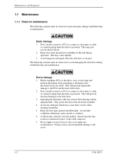
.... 2. A ribbon type cable has one or more PCA missing will be observed to pin 1 of the drive. 2. Don't install or remove a PCA or connect or disconnect a cable or connector plug when the drive is always connected to prevent injury during troubleshooting or maintenance. Avoid dangerous detergent when the disk drive is powered. Static, Damage 1. This will prevent electrical damage to avoid damaging the disk drive during operation. Maintenance...
.... 2. A ribbon type cable has one or more PCA missing will be observed to pin 1 of the drive. 2. Don't install or remove a PCA or connect or disconnect a cable or connector plug when the drive is always connected to prevent injury during troubleshooting or maintenance. Avoid dangerous detergent when the disk drive is powered. Static, Damage 1. This will prevent electrical damage to avoid damaging the disk drive during operation. Maintenance...
Maintenance Manual
Page 17
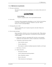
.... Replace the whole disk drive. (4) Service system and repair Fujitsu Limited has a disk drive service system and repair facility. Do not open the DE in the field. (2) Service life In situations where management and handling are correct, the life of the fault − Other information for repair or parts replacement, you should provide related information usually including: a) Model name of disk drive, part number (P/N), disk drive revision number, manufacture serial number (S/N), and date of manufacture of the disk drive b) Circumstances...
.... Replace the whole disk drive. (4) Service system and repair Fujitsu Limited has a disk drive service system and repair facility. Do not open the DE in the field. (2) Service life In situations where management and handling are correct, the life of the fault − Other information for repair or parts replacement, you should provide related information usually including: a) Model name of disk drive, part number (P/N), disk drive revision number, manufacture serial number (S/N), and date of manufacture of the disk drive b) Circumstances...
Maintenance Manual
Page 18
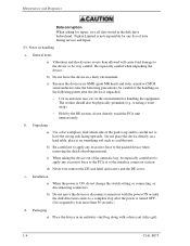
... the DE section, do not change the switch setting, or connecting, or disconnecting connectors. c. in a dusty environment. b) Do not move the device or disconnect connectors with a desiccant (silica gel). 1-4 C141-F073 Installation a) When the power is required to wait more severe than 30 seconds.) d. b. Maintenance and Diagnosis Data corruption When asking for repair, save all data stored in an antistatic vinyl...
... the DE section, do not change the switch setting, or connecting, or disconnecting connectors. c. in a dusty environment. b) Do not move the device or disconnect connectors with a desiccant (silica gel). 1-4 C141-F073 Installation a) When the power is required to wait more severe than 30 seconds.) d. b. Maintenance and Diagnosis Data corruption When asking for repair, save all data stored in an antistatic vinyl...
Maintenance Manual
Page 19
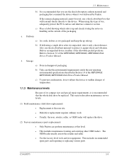
... the non-operating environmental specifications described in Section 1.4 of the allowable packed positions. Storage a) Store in either of the MHV2080AS, MHV2060AS, MHV2040AS Disk Drives Product Manual. The OEM trader usually assists the retailer and seller. • Use the factory level tools and test equipment. b) Take care that will replace the drive. (2) Factory maintenance (parts replacement) • Only Fujitsu can perform maintenance at this type of the MHV2080AS, MHV2060AS, MHV2040AS Disk Drives Product Manual.
... the non-operating environmental specifications described in Section 1.4 of the allowable packed positions. Storage a) Store in either of the MHV2080AS, MHV2060AS, MHV2040AS Disk Drives Product Manual. The OEM trader usually assists the retailer and seller. • Use the factory level tools and test equipment. b) Take care that will replace the drive. (2) Factory maintenance (parts replacement) • Only Fujitsu can perform maintenance at this type of the MHV2080AS, MHV2060AS, MHV2040AS Disk Drives Product Manual.
Maintenance Manual
Page 20
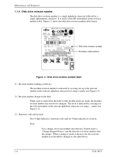
... 1.2). (2) Revision number change in the field When a part is replaced in the relevant alphabetic character row using ¡ marks (see Figure 1.2). (3) Firmware code and revision First 4-digit indicates a firmware code and rest 4-digit indicates its revision. It is stuck on the DE and marked on the revision number label. Disk drive revision number Firmware code/revision Figure 1.1 Disk drive revision number label (1) Revision number marking at the user site, the revision number level...
... 1.2). (2) Revision number change in the field When a part is replaced in the relevant alphabetic character row using ¡ marks (see Figure 1.2). (3) Firmware code and revision First 4-digit indicates a firmware code and rest 4-digit indicates its revision. It is stuck on the DE and marked on the revision number label. Disk drive revision number Firmware code/revision Figure 1.1 Disk drive revision number label (1) Revision number marking at the user site, the revision number level...
Maintenance Manual
Page 22
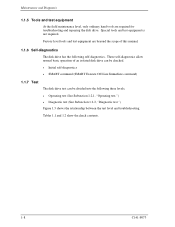
... self-diagnostics • SMART command (SMART Execute Off-Line Immediate command) 1.1.7 Test The disk drive test can be divided into the following self-diagnostics. Tables 1.1 and 1.2 show the check contents. 1-8 C141-F073 These self-diagnostics allow normal basic operation of this manual. 1.1.6 Self-diagnostics The disk drive has the following three levels. • Operating test (See Subsection 1.2.1, "Operating test.") • Diagnostic test (See Subsection 1.2.2, "Diagnostic test.") Figure 1.3 shows the relationship between the test level and troubleshooting. Factory...
... self-diagnostics • SMART command (SMART Execute Off-Line Immediate command) 1.1.7 Test The disk drive test can be divided into the following self-diagnostics. Tables 1.1 and 1.2 show the check contents. 1-8 C141-F073 These self-diagnostics allow normal basic operation of this manual. 1.1.6 Self-diagnostics The disk drive has the following three levels. • Operating test (See Subsection 1.2.1, "Operating test.") • Diagnostic test (See Subsection 1.2.2, "Diagnostic test.") Figure 1.3 shows the relationship between the test level and troubleshooting. Factory...
Maintenance Manual
Page 24
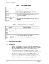
... that the disk drive is the cause, replace the drive. 1.2 Operation Confirmation 1.2.1 Operation test When the host computer is processing data, the disk drive monitors disk drive operation errors including data, command, and seek errors. Any of these bits are normal, in spite of these bits. (Normal) (1) Check whether vibration is the cause, replace the disk drive. To ascertain the cause of the way the disk drive is mounted. (2) Check the power, cable, and connector. (3) If...
... that the disk drive is the cause, replace the drive. 1.2 Operation Confirmation 1.2.1 Operation test When the host computer is processing data, the disk drive monitors disk drive operation errors including data, command, and seek errors. Any of these bits are normal, in spite of these bits. (Normal) (1) Check whether vibration is the cause, replace the disk drive. To ascertain the cause of the way the disk drive is mounted. (2) Check the power, cable, and connector. (3) If...
Maintenance Manual
Page 25
... performed at the user site to isolate the reported failure to the factory for a disk drive failure at this level, accurately reproduce the condition that the whole drive be replaced in Subsection 1.1.3. Usually, troubleshooting is used . Then, by a factory engineer and not where the failure was removed, the failure is elsewhere in the test at field maintenance level described in maintenance of the disk drive host system. 1.2.2 Diagnostic test The diagnostic test...
... performed at the user site to isolate the reported failure to the factory for a disk drive failure at this level, accurately reproduce the condition that the whole drive be replaced in Subsection 1.1.3. Usually, troubleshooting is used . Then, by a factory engineer and not where the failure was removed, the failure is elsewhere in the test at field maintenance level described in maintenance of the disk drive host system. 1.2.2 Diagnostic test The diagnostic test...
Maintenance Manual
Page 26
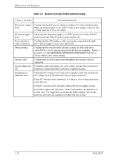
... Diagnosis Table 1.3 System level and field troubleshooting Check to be made Recommended work DC power voltage level DC power ripple noise Power-interface cable connection Switch setting System cable System diagnostic test Intermittent or indefinite error Confirm that all cable connections throughout the system correctly connected. If possible, replace the disk drive. Check that the maximum ripple at the disk drive control PCA is within ±5% of the power supply connector, the +5 VDC must be 4.75...
... Diagnosis Table 1.3 System level and field troubleshooting Check to be made Recommended work DC power voltage level DC power ripple noise Power-interface cable connection Switch setting System cable System diagnostic test Intermittent or indefinite error Confirm that all cable connections throughout the system correctly connected. If possible, replace the disk drive. Check that the maximum ripple at the disk drive control PCA is within ±5% of the power supply connector, the +5 VDC must be 4.75...
Maintenance Manual
Page 27
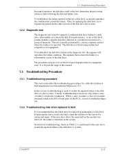
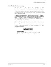
... test, the reappearance test is performed by adding the voltage/temperature load using a disk drive tester or tools according to be opened in the field. As this maintenance level is beyond the scope of failure. To shorten the troubleshooting time and repairing time, gather the data, such as environmental data and other information, from the user and then return the failed drive to the factory to repair. 1.3 Troubleshooting Procedure 1.3.3 Troubleshooting at factory When the trouble...
... test, the reappearance test is performed by adding the voltage/temperature load using a disk drive tester or tools according to be opened in the field. As this maintenance level is beyond the scope of failure. To shorten the troubleshooting time and repairing time, gather the data, such as environmental data and other information, from the user and then return the failed drive to the factory to repair. 1.3 Troubleshooting Procedure 1.3.3 Troubleshooting at factory When the trouble...
Maintenance Manual
Page 30
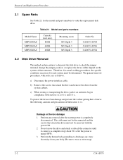
... the power-interface cable. Perform the human body grounding to check the jumper terminal, change the jumper position, or replace the device differ depend on the system cabinet structure. To protect the device from damage and prevent the worker getting hurt, observe the following cautions and precautions in compliance with notes, are as follows. Table 2.1 Model and parts numbers Model Name MHV2080AS MHV2060AS MHV2040AS Capacity (user area...
... the power-interface cable. Perform the human body grounding to check the jumper terminal, change the jumper position, or replace the device differ depend on the system cabinet structure. To protect the device from damage and prevent the worker getting hurt, observe the following cautions and precautions in compliance with notes, are as follows. Table 2.1 Model and parts numbers Model Name MHV2080AS MHV2060AS MHV2040AS Capacity (user area...
Maintenance Manual
Page 31
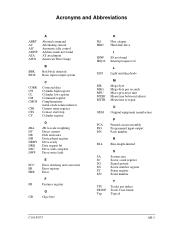
... current Disk enclosure Device/head register Drive ready Data request bit Drive seek complete Drive write fault E ECC Error checking and correction ER Error register ERR Error F FR Features register G GB Giga byte HA HDD H Host adapter Hard disk drive IDNF IRQ14 I ID not found Interrupt request 14 L LED Light emitting diode MB MB/s MPU MTBF MTTR M Mega-byte Mega-byte per seconds Micro processor unit Mean time between failures Mean time to repair...
... current Disk enclosure Device/head register Drive ready Data request bit Drive seek complete Drive write fault E ECC Error checking and correction ER Error register ERR Error F FR Features register G GB Giga byte HA HDD H Host adapter Hard disk drive IDNF IRQ14 I ID not found Interrupt request 14 L LED Light emitting diode MB MB/s MPU MTBF MTTR M Mega-byte Mega-byte per seconds Micro processor unit Mean time between failures Mean time to repair...
Maintenance Manual
Page 33
...general 1-4 on handling 1-4 O Offline self-diagnostics 1-8 Operation configuration 1-10 test 1-10 P Packaging 1-4 dampproof 1-5 Part number 2-2 replacement 1-5 Preventive maintenance 1-3 R Removal and replacement procedure 2-1 Revision, firmware code 1-6 Revision number change in field 1-6, 1-7 mark when delivered 1-6, 1-7 Rule for maintenance 1-2 S Self-diagnostics 1-8 initial 1-8 offline 1-8 Service life 1-3 system and repair 1-3 Spare part 2-2 Status register contents 1-10 Storage 1-5 System level 1-12 and field troubleshooting 1-12 T Test 1-8 equipment 1-8 flowchart 1-9 Tool 1-8 C141-F073...
...general 1-4 on handling 1-4 O Offline self-diagnostics 1-8 Operation configuration 1-10 test 1-10 P Packaging 1-4 dampproof 1-5 Part number 2-2 replacement 1-5 Preventive maintenance 1-3 R Removal and replacement procedure 2-1 Revision, firmware code 1-6 Revision number change in field 1-6, 1-7 mark when delivered 1-6, 1-7 Rule for maintenance 1-2 S Self-diagnostics 1-8 initial 1-8 offline 1-8 Service life 1-3 system and repair 1-3 Spare part 2-2 Status register contents 1-10 Storage 1-5 System level 1-12 and field troubleshooting 1-12 T Test 1-8 equipment 1-8 flowchart 1-9 Tool 1-8 C141-F073...


