Manual/User Guide
Page 14
... Mounting 3-3 3.3 Cable Connections 3-9 3.3.1 Device connector 3-9 3.3.2 Cable connector specifications 3-10 3.3.3 Device connection 3-10 3.3.4 Power supply connector (CN1 3-10 3.4 Jumper Settings 3-11 3.4.1 Location of setting jumpers 3-11 3.4.2 Factory default setting 3-12 3.4.3 Master drive-slave drive setting 3-12 3.4.4 CSEL setting 3-13 3.4.5 Power Up in Standby setting 3-14 CHAPTER 4 Theory of Device Operation 4-1 4.1 Outline ...4-2 4.2 Subassemblies 4-2 4.2.1 Disk...4-2 4.2.2 Spindle 4-2 4.2.3 Actuator 4-2 4.2.4 Air filter 4-3 4.3 Circuit Configuration 4-3 4.4 Power-on...
... Mounting 3-3 3.3 Cable Connections 3-9 3.3.1 Device connector 3-9 3.3.2 Cable connector specifications 3-10 3.3.3 Device connection 3-10 3.3.4 Power supply connector (CN1 3-10 3.4 Jumper Settings 3-11 3.4.1 Location of setting jumpers 3-11 3.4.2 Factory default setting 3-12 3.4.3 Master drive-slave drive setting 3-12 3.4.4 CSEL setting 3-13 3.4.5 Power Up in Standby setting 3-14 CHAPTER 4 Theory of Device Operation 4-1 4.1 Outline ...4-2 4.2 Subassemblies 4-2 4.2.1 Disk...4-2 4.2.2 Spindle 4-2 4.2.3 Actuator 4-2 4.2.4 Air filter 4-3 4.3 Circuit Configuration 4-3 4.4 Power-on...
Manual/User Guide
Page 18
... 3.8 Connector locations 3-9 Figure 3.9 Cable connections 3-10 Figure 3.10 Power supply connector pins (CN1 3-11 Figure 3.11 Jumper location 3-11 Figure 3.12 Factory default setting 3-12 Figure 3.13 Jumper setting of master or slave drive 3-12 Figure 3.14 CSEL setting 3-13 Figure 3.15 Example (1) of Cable Select 3-13 Figure 3.16 Example (2) of Cable Select 3-14 Figure 4.1 Figure...
... 3.8 Connector locations 3-9 Figure 3.9 Cable connections 3-10 Figure 3.10 Power supply connector pins (CN1 3-11 Figure 3.11 Jumper location 3-11 Figure 3.12 Factory default setting 3-12 Figure 3.13 Jumper setting of master or slave drive 3-12 Figure 3.14 CSEL setting 3-13 Figure 3.15 Example (1) of Cable Select 3-13 Figure 3.16 Example (2) of Cable Select 3-14 Figure 4.1 Figure...

Manual/User Guide
Page 39
For information about handling this hard disk drive and the system installation procedure, refer to the following Integration Guide. CHAPTER 3 Installation Conditions 3.1 Dimensions 3.2 Mounting 3.3 Cable Connections 3.4 Jumper Settings This chapter gives the external dimensions, installation conditions, surface temperature conditions, cable connections, and switch settings of the hard disk drives. C141-E144 C141-E195-02EN 3-1
For information about handling this hard disk drive and the system installation procedure, refer to the following Integration Guide. CHAPTER 3 Installation Conditions 3.1 Dimensions 3.2 Mounting 3.3 Cable Connections 3.4 Jumper Settings This chapter gives the external dimensions, installation conditions, surface temperature conditions, cable connections, and switch settings of the hard disk drives. C141-E144 C141-E195-02EN 3-1
Manual/User Guide
Page 49
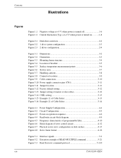
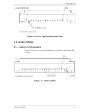
3.4 Jumper Settings Figure 3.10 Power supply connector pins (CN1) 3.4 Jumper Settings 3.4.1 Location of setting jumpers Figure 3.11 shows the location of the jumpers to select drive configuration and functions. Figure 3.11 Jumper location C141-E195-02EN 3-11
3.4 Jumper Settings Figure 3.10 Power supply connector pins (CN1) 3.4 Jumper Settings 3.4.1 Location of setting jumpers Figure 3.11 shows the location of the jumpers to select drive configuration and functions. Figure 3.11 Jumper location C141-E195-02EN 3-11
Manual/User Guide
Page 50
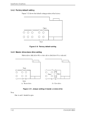
Installation Conditions 3.4.2 Factory default setting Figure 3.12 shows the default setting position at the factory. Open 1 CA 2 DB Open (a) Master drive 1 CA Open Short 2 DB (b) Slave drive Figure 3.13 Jumper setting of master or slave drive Note: Pins A and C should be open. 3-12 C141-E195-02EN Open Figure 3.12 Factory default setting 3.4.3 Master drive-slave drive setting Master drive (disk drive #0) or slave drive (disk drive #1) is selected.
Installation Conditions 3.4.2 Factory default setting Figure 3.12 shows the default setting position at the factory. Open 1 CA 2 DB Open (a) Master drive 1 CA Open Short 2 DB (b) Slave drive Figure 3.13 Jumper setting of master or slave drive Note: Pins A and C should be open. 3-12 C141-E195-02EN Open Figure 3.12 Factory default setting 3.4.3 Master drive-slave drive setting Master drive (disk drive #0) or slave drive (disk drive #1) is selected.
Manual/User Guide
Page 51
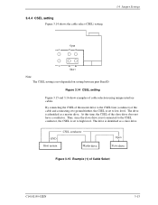
... the CSEL Line (conducer) of cable selection using unique interface cables. The drive is identified as a slave drive. 3.4.4 CSEL setting Figure 3.14 shows the cable select (CSEL) setting. 3.4 Jumper Settings Open 1 CA 2 DB Short Note: The CSEL setting is set to low level. Figure 3.14 CSEL setting Figure 3.15 and 3.16 show examples of the cable and connecting it...
... the CSEL Line (conducer) of cable selection using unique interface cables. The drive is identified as a slave drive. 3.4.4 CSEL setting Figure 3.14 shows the cable select (CSEL) setting. 3.4 Jumper Settings Open 1 CA 2 DB Short Note: The CSEL setting is set to low level. Figure 3.14 CSEL setting Figure 3.15 and 3.16 show examples of the cable and connecting it...

Manual/User Guide
Page 111
...cable). Bits 12-8: In the case of Device 1. '00' = Reserved '01' = Using a jumper. Bit 7-0: Supportable Ultra DMA transfer mode Bit 5: '1' = Supports the Mode 5 Bit 4: '1'... 2 Bit 1: '1' = Supports the Mode 1 Bit 0: '1' = Supports the Mode 0 *19 WORD 89 MHT2080AH = X'28': 80 minutes MHT2060AH = X'20': 60 minutes MHT2040AH = X'14': 40 minutes *20 WORD 93 Bits...CBLID- C141-E195-02EN 5-41 Bit 10: '1' = Mode 2 is selected. is set. Bit 12: Reserved Bit 11: '1' = Device asserts PDIAG-. Bit 10, 9: Method...slave drive), a valid value is a lower level than VIH (80-conductor cable). '0' = ...
...cable). Bits 12-8: In the case of Device 1. '00' = Reserved '01' = Using a jumper. Bit 7-0: Supportable Ultra DMA transfer mode Bit 5: '1' = Supports the Mode 5 Bit 4: '1'... 2 Bit 1: '1' = Supports the Mode 1 Bit 0: '1' = Supports the Mode 0 *19 WORD 89 MHT2080AH = X'28': 80 minutes MHT2060AH = X'20': 60 minutes MHT2040AH = X'14': 40 minutes *20 WORD 93 Bits...CBLID- C141-E195-02EN 5-41 Bit 10: '1' = Mode 2 is selected. is set. Bit 12: Reserved Bit 11: '1' = Device asserts PDIAG-. Bit 10, 9: Method...slave drive), a valid value is a lower level than VIH (80-conductor cable). '0' = ...

Manual/User Guide
Page 112
.... Bit 2, 1: Method for deciding the device No. Bit 0: '1'= (In the case of Device 0. '00' = Reserved '01' = Using a jumper. '10' = Using the CSEL signal. '11' = Other method. Bit 7-0: X'XX' Current set . FE-C0: Performance mode BF-80: Acoustic mode 00: Acoustic management is unused it. (It is same as "FE-CO...") *22 WORD 100-103 When "48 bit LBA" of the option (customize) is supported, same number of Device 0 (master drive), a valid value is set value. Bit 5: '1' = Device 0, assertion of PDIAG- Bit 4: '1' = Device 0, assertion of DASP-
.... Bit 2, 1: Method for deciding the device No. Bit 0: '1'= (In the case of Device 0. '00' = Reserved '01' = Using a jumper. '10' = Using the CSEL signal. '11' = Other method. Bit 7-0: X'XX' Current set . FE-C0: Performance mode BF-80: Acoustic mode 00: Acoustic management is unused it. (It is same as "FE-CO...") *22 WORD 100-103 When "48 bit LBA" of the option (customize) is supported, same number of Device 0 (master drive), a valid value is set value. Bit 5: '1' = Device 0, assertion of PDIAG- Bit 4: '1' = Device 0, assertion of DASP-

