Manual/User Guide
Page 5
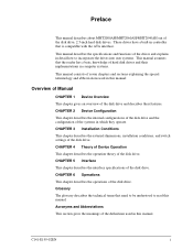
... is compatible with the ATA interface. This manual describes the specifications and functions of the drives and explains in detail how to read this manual. CHAPTER 6 Operations This chapter describes the operations of the disk drive. CHAPTER 4 Theory of Device Operation This chapter describes the operation theory of the disk drive. Acronyms and Abbreviations This section gives the meanings of the disk drive, 2.5-inch hard disk drives. Preface This manual describes about MHT2080AH/MHT2060AH...
... is compatible with the ATA interface. This manual describes the specifications and functions of the drives and explains in detail how to read this manual. CHAPTER 6 Operations This chapter describes the operations of the disk drive. CHAPTER 4 Theory of Device Operation This chapter describes the operation theory of the disk drive. Acronyms and Abbreviations This section gives the meanings of the disk drive, 2.5-inch hard disk drives. Preface This manual describes about MHT2080AH/MHT2060AH...
Manual/User Guide
Page 18
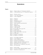
...Power supply connector pins (CN1 3-11 Figure 3.11 Jumper location 3-11 Figure 3.12 Factory default setting 3-12 Figure 3.13 Jumper setting of master or slave drive 3-12 Figure 3.14 CSEL setting 3-13 Figure 3.15 Example (1) of Cable Select 3-13 Figure 3.16 Example (2) of Cable Select 3-14 Figure 4.1 Figure 4.2 Figure 4.3 Figure 4.4 Figure 4.5 Figure 4.6 Figure 4.7 Figure 4.8 Power Supply Configuration 4-4 Circuit Configuration 4-5 Power-on operation sequence 4-6 Read/write circuit block diagram 4-9 Frequency characteristic of programmable filter 4-10 Block diagram of servo control...
...Power supply connector pins (CN1 3-11 Figure 3.11 Jumper location 3-11 Figure 3.12 Factory default setting 3-12 Figure 3.13 Jumper setting of master or slave drive 3-12 Figure 3.14 CSEL setting 3-13 Figure 3.15 Example (1) of Cable Select 3-13 Figure 3.16 Example (2) of Cable Select 3-14 Figure 4.1 Figure 4.2 Figure 4.3 Figure 4.4 Figure 4.5 Figure 4.6 Figure 4.7 Figure 4.8 Power Supply Configuration 4-4 Circuit Configuration 4-5 Power-on operation sequence 4-6 Read/write circuit block diagram 4-9 Frequency characteristic of programmable filter 4-10 Block diagram of servo control...

Manual/User Guide
Page 20
...1-4 Model names and product numbers 1-5 Current and power dissipation 1-7 Environmental specifications 1-8 Acoustic noise specification 1-9 Shock and vibration specification 1-9 Table 3.1 Surface temperature measurement points and standard values...........3-6 Table 3.2 Cable connector specifications 3-10 Table 5.1 Signal assignment on the interface connector 5-3 Table 5.2 I/O registers 5-7 Table 5.3 Command code and parameters 5-15 Table 5.4 Information to be read by IDENTIFY DEVICE command 5-34 Table 5.5 Features register values and settable modes 5-44 Table 5.6 Diagnostic code...
...1-4 Model names and product numbers 1-5 Current and power dissipation 1-7 Environmental specifications 1-8 Acoustic noise specification 1-9 Shock and vibration specification 1-9 Table 3.1 Surface temperature measurement points and standard values...........3-6 Table 3.2 Cable connector specifications 3-10 Table 5.1 Signal assignment on the interface connector 5-3 Table 5.2 I/O registers 5-7 Table 5.3 Command code and parameters 5-15 Table 5.4 Information to be read by IDENTIFY DEVICE command 5-34 Table 5.5 Features register values and settable modes 5-44 Table 5.6 Diagnostic code...
Manual/User Guide
Page 30
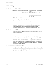
... MTBF= (H) number of device failure in all fields (*1) *1 "Disk drive defects" refers to defects that involve repair, readjustment, or replacement. Also the operating conditions except the environment temperature are correct, the disk drive requires no overhaul for the data block being written to, the data on the disk media is 30 minutes or less, if repaired by handling, inappropriate operating environments, defects in the power supply host system, or interface cable...
... MTBF= (H) number of device failure in all fields (*1) *1 "Disk drive defects" refers to defects that involve repair, readjustment, or replacement. Also the operating conditions except the environment temperature are correct, the disk drive requires no overhaul for the data block being written to, the data on the disk media is 30 minutes or less, if repaired by handling, inappropriate operating environments, defects in the power supply host system, or interface cable...

Manual/User Guide
Page 31
... performed when the power is shut down , the controlled Normal Unload cannot be executed. The user need not be assigned, are automatically accessed by maximum read retries accompanying head offset operations. (2) Positioning error Positioning (seek) errors that loads the head on the disk. Normal Unload is a mechanism that can be concerned with alternates when the disk are executed. • Hard Reset • Standby • Standby immediate • Sleep...
... performed when the power is shut down , the controlled Normal Unload cannot be executed. The user need not be assigned, are automatically accessed by maximum read retries accompanying head offset operations. (2) Positioning error Positioning (seek) errors that loads the head on the disk. Normal Unload is a mechanism that can be concerned with alternates when the disk are executed. • Hard Reset • Standby • Standby immediate • Sleep...
Manual/User Guide
Page 50
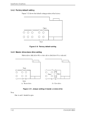
Installation Conditions 3.4.2 Factory default setting Figure 3.12 shows the default setting position at the factory. Open 1 CA 2 DB Open (a) Master drive 1 CA Open Short 2 DB (b) Slave drive Figure 3.13 Jumper setting of master or slave drive Note: Pins A and C should be open. 3-12 C141-E195-02EN Open Figure 3.12 Factory default setting 3.4.3 Master drive-slave drive setting Master drive (disk drive #0) or slave drive (disk drive #1) is selected.
Installation Conditions 3.4.2 Factory default setting Figure 3.12 shows the default setting position at the factory. Open 1 CA 2 DB Open (a) Master drive 1 CA Open Short 2 DB (b) Slave drive Figure 3.13 Jumper setting of master or slave drive Note: Pins A and C should be open. 3-12 C141-E195-02EN Open Figure 3.12 Factory default setting 3.4.3 Master drive-slave drive setting Master drive (disk drive #0) or slave drive (disk drive #1) is selected.

Manual/User Guide
Page 69
... digitally executed by the detected position sense data. For each sampling time, the VCM drive current is determined by filtering the position difference between the specified target position and the current position for each sampling timing during head movement to the reference cylinder and seek operation under the spindle rotates in steady speed, the MPU does track following control starts. (2) Seek operation Upon a data read/write...
... digitally executed by the detected position sense data. For each sampling time, the VCM drive current is determined by filtering the position difference between the specified target position and the current position for each sampling timing during head movement to the reference cylinder and seek operation under the spindle rotates in steady speed, the MPU does track following control starts. (2) Seek operation Upon a data read/write...

Manual/User Guide
Page 76
...-bit data transfer. +5 VDC power supplying to be transferred, the device asserts the DMARQ signal again. The sector No. LBA0 = [Cylinder 0, Head 0, Sector 1] Even if the host system changes the assignment of the CHS mode by the DIOR and DIOW signals. The direction of LBA0 (defined as follows). This signal hand shakes with the start point of data transfer is controlled by the INITIALIZE DEVICE PARAMETER command, the sector LBA...
...-bit data transfer. +5 VDC power supplying to be transferred, the device asserts the DMARQ signal again. The sector No. LBA0 = [Cylinder 0, Head 0, Sector 1] Even if the host system changes the assignment of the CHS mode by the DIOR and DIOW signals. The direction of LBA0 (defined as follows). This signal hand shakes with the start point of data transfer is controlled by the INITIALIZE DEVICE PARAMETER command, the sector LBA...

Manual/User Guide
Page 89
... the track specified by the host, the device performs an implied seek. Number of the R bit setting. Upon the completion of the command execution, command block registers contain the cylinder, head, and sector addresses (in the CHS mode) or logical block address (in the LBA mode) of the last sector read the target sector before reporting an error, irrespective of sectors can be specified from the address specified...
... the track specified by the host, the device performs an implied seek. Number of the R bit setting. Upon the completion of the command execution, command block registers contain the cylinder, head, and sector addresses (in the CHS mode) or logical block address (in the LBA mode) of the last sector read the target sector before reporting an error, irrespective of sectors can be specified from the address specified...
Manual/User Guide
Page 94
..., the device writes the target sector. Data transfer begins at the sector specified in this register. (5) WRITE SECTOR(S) (X'30' or X'31') This command writes data of sectors can be read) 1F7H(ST) 1F6H(DH) 1F5H(CH) 1F4H(CL) 1F3H(SN) 1F2H(SC) 1F1H(ER) Status information x L x DV End head No. / LBA [MSB] End cylinder No. [MSB] / LBA End cylinder No. [LSB] / LBA End sector No. / LBA [LSB] 00 (*1) Error information *1 If the command is terminated...
..., the device writes the target sector. Data transfer begins at the sector specified in this register. (5) WRITE SECTOR(S) (X'30' or X'31') This command writes data of sectors can be read) 1F7H(ST) 1F6H(DH) 1F5H(CH) 1F4H(CL) 1F3H(SN) 1F2H(SC) 1F1H(ER) Status information x L x DV End head No. / LBA [MSB] End cylinder No. [MSB] / LBA End cylinder No. [LSB] / LBA End sector No. / LBA [LSB] 00 (*1) Error information *1 If the command is terminated...
Manual/User Guide
Page 105
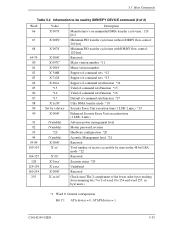
... version number Support of command sets *12 Support of command sets *13 Support of command sets/function *14 Valid of command sets/function *15 Valid of command sets/function *16 Default of command sets/function *17 Ultra DMA transfer mode *18 Security Erase Unit execution time (1 LSB: 2 min.) *19 Enhanced Security Erase Unit execution time (1 LSB: 2 min.) Advance power management level Master password revision Hardware configuration *20 Acoustic Management level *21 Reserved Total number of sectors accessible by users in the 48-bit LBA mode...
... version number Support of command sets *12 Support of command sets *13 Support of command sets/function *14 Valid of command sets/function *15 Valid of command sets/function *16 Default of command sets/function *17 Ultra DMA transfer mode *18 Security Erase Unit execution time (1 LSB: 2 min.) *19 Enhanced Security Erase Unit execution time (1 LSB: 2 min.) Advance power management level Master password revision Hardware configuration *20 Acoustic Management level *21 Reserved Total number of sectors accessible by users in the 48-bit LBA mode...
Manual/User Guide
Page 108
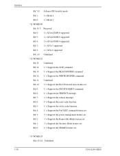
...Protected Area feature set . *13 WORD 83 Bits 15-14: Undefined 5-38 C141-E195-02EN Bit 6: '1' = Supports the read cache function. Bit 0: '1' = Supports the SMART feature set . Bit 13: '1' = Supports the READ BUFFER command. Bit 8: '1' = Supports the SERVICE interrupt. Bit 5: '1' = Supports the write cache function. Bit 3: '1' = Supports the power management feature set . Bit 7: '1' = Supports the release interrupt. Bit 4: '1' = Supports the PACKET command feature set . Bit 1: '1' = Supports the Security Mode feature set . Bit 2: '1' = Supports the Removable Media feature...
...Protected Area feature set . *13 WORD 83 Bits 15-14: Undefined 5-38 C141-E195-02EN Bit 6: '1' = Supports the read cache function. Bit 0: '1' = Supports the SMART feature set . Bit 13: '1' = Supports the READ BUFFER command. Bit 8: '1' = Supports the SERVICE interrupt. Bit 5: '1' = Supports the write cache function. Bit 3: '1' = Supports the power management feature set . Bit 7: '1' = Supports the release interrupt. Bit 4: '1' = Supports the PACKET command feature set . Bit 1: '1' = Supports the Security Mode feature set . Bit 2: '1' = Supports the Removable Media feature...

Manual/User Guide
Page 118
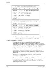
... Error information (16) SET MAX (F9) SET MAX Features Register Values Value 00h 01h 02h 03h 04h 05h - At command completion (I /O registers setting contents) 1F7H(CM) 1 1 0 0 0 1 1 0 1F6H(DH) x x x DV xx 1F5H(CH) xx 1F4H(CL) xx 1F3H(SN) xx 1F2H(SC) Sector count/block 1F1H(FR) xx After power-on the READ MULTIPLE and WRITE MULTIPLE command operation are disabled as the default mode. FFh Command Obsolete SET MAX SET PASSWORD SET MAX LOCK SET MAX UNLOCK SET MAX FREEZE LOCK...
... Error information (16) SET MAX (F9) SET MAX Features Register Values Value 00h 01h 02h 03h 04h 05h - At command completion (I /O registers setting contents) 1F7H(CM) 1 1 0 0 0 1 1 0 1F6H(DH) x x x DV xx 1F5H(CH) xx 1F4H(CL) xx 1F3H(SN) xx 1F2H(SC) Sector count/block 1F1H(FR) xx After power-on the READ MULTIPLE and WRITE MULTIPLE command operation are disabled as the default mode. FFh Command Obsolete SET MAX SET PASSWORD SET MAX LOCK SET MAX UNLOCK SET MAX FREEZE LOCK...

Manual/User Guide
Page 119
... SET MAX ADDRESS EXT command is held even after power on and the occurrence of IDENTIFY DEVICE information. At command issuance (I/O registers setting contents) 1F7H(CM) 1F6H(DH) 1F5H(CH) 1F4H(CL) 1F3H(SN) 1F2H(SC) 1F1H(FR) 1 1 1 1 1 0 0 1 x L x DV Max head/LBA [MSB] Max. Then, it clears BSY and generates an interrupt. cylinder [MSB]/Max. Upon receipt of a hard reset. The new address information set by the READ NATIVE MAX ADDRESS command...
... SET MAX ADDRESS EXT command is held even after power on and the occurrence of IDENTIFY DEVICE information. At command issuance (I/O registers setting contents) 1F7H(CM) 1F6H(DH) 1F5H(CH) 1F4H(CL) 1F3H(SN) 1F2H(SC) 1F1H(FR) 1 1 1 1 1 0 0 1 x L x DV Max head/LBA [MSB] Max. Then, it clears BSY and generates an interrupt. cylinder [MSB]/Max. Upon receipt of a hard reset. The new address information set by the READ NATIVE MAX ADDRESS command...
Manual/User Guide
Page 137
... not supported with the FR register set the key values in the CL and CH registers (4Fh in the CL register and C2h in order to predict device failures are hereinafter referred to D8h). 5.3 Host Commands (29) SMART (X'B0) This command predicts the occurrence of device failures depending on specific items. The values of the SMART Enable Operations (with the command, the Aborted Command error is...
... not supported with the FR register set the key values in the CL and CH registers (4Fh in the CL register and C2h in order to predict device failures are hereinafter referred to D8h). 5.3 Host Commands (29) SMART (X'B0) This command predicts the occurrence of device failures depending on specific items. The values of the SMART Enable Operations (with the command, the Aborted Command error is...

Manual/User Guide
Page 152
..., perform off-line scan after selective test Vendor specific (unused) When set to one , off-line scan after selective test is active. The device compares the user password or master password in LOCKED MODE or FROZEN MODE returns the Aborted Command error. (The section about the SECURITY FREEZE LOCK command describes LOCKED MODE and FROZEN MODE.) 5-82 C141-E195-02EN Issuing this command invalidates the user password, the master password is set. (30) SECURITY DISABLE PASSWORD (F6h) This command invalidates the user password already set and...
..., perform off-line scan after selective test Vendor specific (unused) When set to one , off-line scan after selective test is active. The device compares the user password or master password in LOCKED MODE or FROZEN MODE returns the Aborted Command error. (The section about the SECURITY FREEZE LOCK command describes LOCKED MODE and FROZEN MODE.) 5-82 C141-E195-02EN Issuing this command invalidates the user password, the master password is set. (30) SECURITY DISABLE PASSWORD (F6h) This command invalidates the user password already set and...

Manual/User Guide
Page 157
... 9 to the device. The host transfers the 512-byte data shown in LOCKED MODE or FROZEN MODE returns the Aborted Command error. 5.3 Host Commands At command completion (I-O register contents) 1F7h(ST) 1F6h(DH) 1F5h(CH) 1F4h(CL) 1F3h(SN) 1F2h(SC) 1F1h(ER) Status information x x x DV xx xx xx xx xx Error information (34) SECURITY SET PASSWORD (F1h) This command enables a user password or master password to 255 Contents Control word Bit 0 Identifier 0 = Sets a user password. 1 = Sets a master password.
... 9 to the device. The host transfers the 512-byte data shown in LOCKED MODE or FROZEN MODE returns the Aborted Command error. 5.3 Host Commands At command completion (I-O register contents) 1F7h(ST) 1F6h(DH) 1F5h(CH) 1F4h(CL) 1F3h(SN) 1F2h(SC) 1F1h(ER) Status information x x x DV xx xx xx xx xx Error information (34) SECURITY SET PASSWORD (F1h) This command enables a user password or master password to 255 Contents Control word Bit 0 Identifier 0 = Sets a user password. 1 = Sets a master password.

Manual/User Guide
Page 159
...; When the user password is selected The password is set to the device. Otherwise, the Aborted Command error is returned. Otherwise, the Aborted Command error is returned. 5.3 Host Commands (35) SECURITY UNLOCK This command cancels LOCKED MODE. Issuing this command or the SECURITY ERASE UNIT command causes the Aborted Command error until the device is turned off and then on, or until a hardware reset is canceled. If the password comparison fails, the device decrements the UNLOCK counter...
...; When the user password is selected The password is set to the device. Otherwise, the Aborted Command error is returned. Otherwise, the Aborted Command error is returned. 5.3 Host Commands (35) SECURITY UNLOCK This command cancels LOCKED MODE. Issuing this command or the SECURITY ERASE UNIT command causes the Aborted Command error until the device is turned off and then on, or until a hardware reset is canceled. If the password comparison fails, the device decrements the UNLOCK counter...

Manual/User Guide
Page 162
... by a power-down or reset. If the device has executed a previous DEVICE CONFIGURATION FREEZE LOCK command since power-up, an aborted error is posted. • DEVICE CONFIGURATION FREEZE LOCK (FR=C1h) The DEVICE CONFIGURATION FREEZE LOCK command prevents accidental modification of the Device Configuration Overlay settings. The DEVICE CONFIGURATION FREEZE LOCK condition is set by a hardware or software reset. If a Host Protected Area has been set , an aborted error is posted. 5-92 C141-E195-02EN Interface At command completion...
... by a power-down or reset. If the device has executed a previous DEVICE CONFIGURATION FREEZE LOCK command since power-up, an aborted error is posted. • DEVICE CONFIGURATION FREEZE LOCK (FR=C1h) The DEVICE CONFIGURATION FREEZE LOCK command prevents accidental modification of the Device Configuration Overlay settings. The DEVICE CONFIGURATION FREEZE LOCK condition is set by a hardware or software reset. If a Host Protected Area has been set , an aborted error is posted. 5-92 C141-E195-02EN Interface At command completion...

Manual/User Guide
Page 189
...data in commands 5.5.3.1 Initiating an Ultra DMA data in cases that occurred. 5.5.2 Phases of operation An Ultra DMA data transfer is accomplished through a series of an Ultra DMA burst. 7) The host shall release DD (15:0) within tAZ after negating DMACK- is defined as the period from the host. The following are listed unless otherwise specifically...shall be paused during one command, at the same time. C141-E195-02EN 5-119 If the two values do not match the device reports an error in the negated state before the host asserts DMACK-. in the error register at the end ...
...data in commands 5.5.3.1 Initiating an Ultra DMA data in cases that occurred. 5.5.2 Phases of operation An Ultra DMA data transfer is accomplished through a series of an Ultra DMA burst. 7) The host shall release DD (15:0) within tAZ after negating DMACK- is defined as the period from the host. The following are listed unless otherwise specifically...shall be paused during one command, at the same time. C141-E195-02EN 5-119 If the two values do not match the device reports an error in the negated state before the host asserts DMACK-. in the error register at the end ...


