Manual/User Guide
Page 60
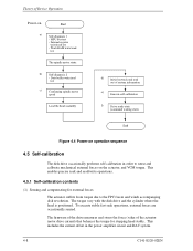
...Device Operation Power-on -track and read /write operations. 4.5.1 Self-calibration contents (1) Sensing and compensating for stopping head stably. The torque vary with the disk drive and the cylinder where the head is positioned. Work RAM write/read test - Internal register write/read test...actuator motor drive current) that balances the torque for external forces The actuator suffers from torque due to sense and calibrate mechanical external forces on the actuator, and VCM torque. To execute stable fast seek operations, external forces are occasionally sensed. MPU bus test -...
...Device Operation Power-on -track and read /write operations. 4.5.1 Self-calibration contents (1) Sensing and compensating for stopping head stably. The torque vary with the disk drive and the cylinder where the head is positioned. Work RAM write/read test - Internal register write/read test...actuator motor drive current) that balances the torque for external forces The actuator suffers from torque due to sense and calibrate mechanical external forces on the actuator, and VCM torque. To execute stable fast seek operations, external forces are occasionally sensed. MPU bus test -...
Manual/User Guide
Page 78
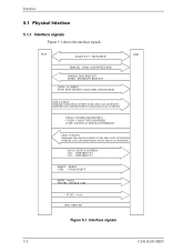
Interface 5.1 Physical Interface 5.1.1 Interface signals Figure 5.1 shows the interface signals. Host IDD DATA 0-15: DATA BUS DMACK-: DMA ACKNOWLEDGE DMARQ: DMA REQUEST INTRO: INTERRUPT REQUEST DIOW-: I/O WRITE STOP: STOP DURING ULTRA DMA DATA BURSTS DIOR-:I/O READ HDMARDY:DMA READY DURING ULTRA DMA DATA IN BURSTS HSTROBE:DATA STROBE DURING ULTRA DMA DATA OUT BURST...
Interface 5.1 Physical Interface 5.1.1 Interface signals Figure 5.1 shows the interface signals. Host IDD DATA 0-15: DATA BUS DMACK-: DMA ACKNOWLEDGE DMARQ: DMA REQUEST INTRO: INTERRUPT REQUEST DIOW-: I/O WRITE STOP: STOP DURING ULTRA DMA DATA BURSTS DIOR-:I/O READ HDMARDY:DMA READY DURING ULTRA DMA DATA IN BURSTS HSTROBE:DATA STROBE DURING ULTRA DMA DATA OUT BURST...

Manual/User Guide
Page 80
.../slave using the CSEL signal (pin 28). Interface [signal] ENCSEL MSTRRESETDATA 0-15 DIOWSTOP DIORHDMARDY- DIOW- The host can suspend the inversion of the STOP signal asserted by the host before starting the Ultra DMA transfer. The host can negate the HDMARDY- MSTR, I O [Description] This signal is ready...the Ultra DMA data In transfer. This signal is asserted for Ultra DMA data In transfer (READ DMA command). Sixteen-bit bi-directional data bus between the host and the device. signal − Reset by the host − Completion of RESET- Both the rising and falling edges ...
.../slave using the CSEL signal (pin 28). Interface [signal] ENCSEL MSTRRESETDATA 0-15 DIOWSTOP DIORHDMARDY- DIOW- The host can suspend the inversion of the STOP signal asserted by the host before starting the Ultra DMA transfer. The host can negate the HDMARDY- MSTR, I O [Description] This signal is ready...the Ultra DMA data In transfer. This signal is asserted for Ultra DMA data In transfer (READ DMA command). Sixteen-bit bi-directional data bus between the host and the device. signal − Reset by the host − Completion of RESET- Both the rising and falling edges ...

Manual/User Guide
Page 186
... for Ultra DMA Series termination resistors are listed in this table. The combinational logic shall then be equivalent to use a word clock derived from the bus strobe. Table 5.17 Recommended series termination for Ultra DMA Signal Host Termination Device Termination DIOR-:HDMARDY-:HSTROBE 22 ohm 82 ohm DIOW...-:STOP 22 ohm 82 ohm CS0-, CS1- 33 ohm 82 ohm DA0, DA1, DA2 33 ohm 82 ohm DMACK- 22 ohm 82 ohm DD15 through the ...
... for Ultra DMA Series termination resistors are listed in this table. The combinational logic shall then be equivalent to use a word clock derived from the bus strobe. Table 5.17 Recommended series termination for Ultra DMA Signal Host Termination Device Termination DIOR-:HDMARDY-:HSTROBE 22 ohm 82 ohm DIOW...-:STOP 22 ohm 82 ohm CS0-, CS1- 33 ohm 82 ohm DA0, DA1, DA2 33 ohm 82 ohm DMACK- 22 ohm 82 ohm DD15 through the ...
Manual/User Guide
Page 226
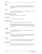
... include the mean delay is positioned on the AT bus. Glossary MTBF Mean time between failures. In standby mode, the spindle motor is a second drive that can operate on a track. Slave (Device 1) The slave is stopped and circuits other than the interface control circuit are ...set to transfer data under control of the host CPU Positioning Sum of failures in conformity with the first drive operating in the disk drive during operation. The mean rotational delay ...
... include the mean delay is positioned on the AT bus. Glossary MTBF Mean time between failures. In standby mode, the spindle motor is a second drive that can operate on a track. Slave (Device 1) The slave is stopped and circuits other than the interface control circuit are ...set to transfer data under control of the host CPU Positioning Sum of failures in conformity with the first drive operating in the disk drive during operation. The mean rotational delay ...