Manual/User Guide
Page 4
Related Standards Product specifications and functions described in this manual takes precedence. Document number T10/1236D Rev.20 [NCITS.351:2001] T10/996D Rev.8c [NCITS.306:1998] T10/1157D Rev.20 T10/1365D Rev.7 Title SCSI Primary Commands-2 (SPC-2) SCSI-3 Block Commands (SBC) SCSI Architecture Model-2 (SAM-2) SCSI Parallel Interface-4 (SPI-4) *1 ANSI = American National Standard Institute In case of conflict between this manual and any referenced document, this manual comply with the following ANSI (*1) standards. ii C141-E166
Related Standards Product specifications and functions described in this manual takes precedence. Document number T10/1236D Rev.20 [NCITS.351:2001] T10/996D Rev.8c [NCITS.306:1998] T10/1157D Rev.20 T10/1365D Rev.7 Title SCSI Primary Commands-2 (SPC-2) SCSI-3 Block Commands (SBC) SCSI Architecture Model-2 (SAM-2) SCSI Parallel Interface-4 (SPI-4) *1 ANSI = American National Standard Institute In case of conflict between this manual and any referenced document, this manual comply with the following ANSI (*1) standards. ii C141-E166
Manual/User Guide
Page 5
... defects. This chapter also describes diagnostic methods for installing MAP series disk drives. APPENDIX A to install MAP series disk drives. PREFACE This manual describes the MAP3147NC/NP, MAP3735NC/NP and MAP3367NC/NP (hereafter, MAP series), 3.5 type fixed disk drives with an embedded SCSI controller. Chapter 2 SPECIFICATIONS This chapter gives detailed specifications of interface connector. Chapter...
... defects. This chapter also describes diagnostic methods for installing MAP series disk drives. APPENDIX A to install MAP series disk drives. PREFACE This manual describes the MAP3147NC/NP, MAP3735NC/NP and MAP3367NC/NP (hereafter, MAP series), 3.5 type fixed disk drives with an embedded SCSI controller. Chapter 2 SPECIFICATIONS This chapter gives detailed specifications of interface connector. Chapter...
Manual/User Guide
Page 8
...Electrostatics Discharge) may cause an irreparable fault. 6-15 Data loss Save data stored on , the overcurrent protection fuse of the SCSI connectors. Fujitsu 6-7 does not assume responsibility if data is not provided. Be careful of the insertion orientation of the terminating resistor power ... with the terminating resistor is required to pin 1. Do not use solvents to clean a disk drive assembly. 5. Opening the disk 6-6 enclosure may cause the damage to the disk drive, turn off before connecting or 6-5 disconnecting a cable, connector, or plug. 2. To avoid ...
...Electrostatics Discharge) may cause an irreparable fault. 6-15 Data loss Save data stored on , the overcurrent protection fuse of the SCSI connectors. Fujitsu 6-7 does not assume responsibility if data is not provided. Be careful of the insertion orientation of the terminating resistor power ... with the terminating resistor is required to pin 1. Do not use solvents to clean a disk drive assembly. 5. Opening the disk 6-6 enclosure may cause the damage to the disk drive, turn off before connecting or 6-5 disconnecting a cable, connector, or plug. 2. To avoid ...
Manual/User Guide
Page 11
... Standard Features ...1-2 1.2 Hardware Structure...1-6 1.3 System Configuration ...1-9 CHAPTER 2 SPECIFICATIONS 2-1 2.1 Hardware Specifications...2-1 2.1.1 Model name and order number 2-1 2.1.2 Function specifications...2-2 2.1.3 Environmental specifications 2-4 2.1.4 Error rate ...2-5 2.1.5 Reliability...2-5 2.2 SCSI Function Specifications 2-7 CHAPTER 3 DATA FORMAT 3-1 3.1 Data Space...3-1 3.1.1 Cylinder configuration...3-1 3.1.2 Alternate spare area...3-4 3.1.3 Track format...3-5 3.1.4 Sector format ...3-7 3.1.5 Format capacity ...3-9 3.2 Logical Data Block Addressing 3-9 3.3 Defect...
... Standard Features ...1-2 1.2 Hardware Structure...1-6 1.3 System Configuration ...1-9 CHAPTER 2 SPECIFICATIONS 2-1 2.1 Hardware Specifications...2-1 2.1.1 Model name and order number 2-1 2.1.2 Function specifications...2-2 2.1.3 Environmental specifications 2-4 2.1.4 Error rate ...2-5 2.1.5 Reliability...2-5 2.2 SCSI Function Specifications 2-7 CHAPTER 3 DATA FORMAT 3-1 3.1 Data Space...3-1 3.1.1 Cylinder configuration...3-1 3.1.2 Alternate spare area...3-4 3.1.3 Track format...3-5 3.1.4 Sector format ...3-7 3.1.5 Format capacity ...3-9 3.2 Logical Data Block Addressing 3-9 3.3 Defect...
Manual/User Guide
Page 12
... Mounting procedures...5-10 5.5 Connecting Cables...5-11 5.6 Confirming Operations after Installation and Preparation for use 5-12 5.6.1 Confirming initial operations 5-12 5.6.2 Checking SCSI connection 5-13 5.6.3 Formatting ...5-16 5.6.4 Setting parameters ...5-18 5.7 Dismounting Drives...5-22 5.8 Spare Disk Drive ...5-22 CHAPTER 6 DIAGNOSTICS AND MAINTENANCE 6-1 6.1 Diagnostics ...6-1 6.1.1 Self-diagnostics ...6-1 6.1.2 Test programs...6-4 6.2 Maintenance Information 6-5 6.2.1 Precautions ...6-5 6.2.2 Maintenance requirements 6-6 6.2.3 Maintenance levels ...6-8 6.2.4 Revision numbers...
... Mounting procedures...5-10 5.5 Connecting Cables...5-11 5.6 Confirming Operations after Installation and Preparation for use 5-12 5.6.1 Confirming initial operations 5-12 5.6.2 Checking SCSI connection 5-13 5.6.3 Formatting ...5-16 5.6.4 Setting parameters ...5-18 5.7 Dismounting Drives...5-22 5.8 Spare Disk Drive ...5-22 CHAPTER 6 DIAGNOSTICS AND MAINTENANCE 6-1 6.1 Diagnostics ...6-1 6.1.1 Self-diagnostics ...6-1 6.1.2 Test programs...6-4 6.2 Maintenance Information 6-5 6.2.1 Precautions ...6-5 6.2.2 Maintenance requirements 6-6 6.2.3 Maintenance levels ...6-8 6.2.4 Revision numbers...
Manual/User Guide
Page 13
6.3.3 6.4 6.4.1 6.4.2 6.4.3 6.4.4 6.4.5 Diagnostic test ...6-12 Troubleshooting Procedures 6-13 Outline of troubleshooting procedures 6-13 Troubleshooting with disk drive replacement in the field 6-13 Troubleshooting at the repair site 6-15 Troubleshooting with parts replacement in the factory 6-16 Finding possibly faulty...1D-00): Disk read error 7-4 7.2.4 Sense data (5-2x-xx), (5-3D-00), (5-90-00), (B-47-xx), (B-49-00), (B-4D-xx) and (B-4E-00): SCSI interface error 7-4 APPENDIX A SETTING TERMINALS A-1 A.1 Setting Terminals (on NP model only A-2 APPENDIX B CONNECTOR SIGNAL ALLOCATION...
6.3.3 6.4 6.4.1 6.4.2 6.4.3 6.4.4 6.4.5 Diagnostic test ...6-12 Troubleshooting Procedures 6-13 Outline of troubleshooting procedures 6-13 Troubleshooting with disk drive replacement in the field 6-13 Troubleshooting at the repair site 6-15 Troubleshooting with parts replacement in the factory 6-16 Finding possibly faulty...1D-00): Disk read error 7-4 7.2.4 Sense data (5-2x-xx), (5-3D-00), (5-90-00), (B-47-xx), (B-49-00), (B-4D-xx) and (B-4E-00): SCSI interface error 7-4 APPENDIX A SETTING TERMINALS A-1 A.1 Setting Terminals (on NP model only A-2 APPENDIX B CONNECTOR SIGNAL ALLOCATION...
Manual/User Guide
Page 15
FIGURES Figure 1.1 Figure 1.2 Figure 1.3 Figure 1.4 page NC model drives outer view 1-6 NP model drives outer view 1-6 Disk/head configuration...1-7 System configuration ...1-9 Figure 3.1 Figure 3.2 Figure 3.3 Figure 3.4 Figure 3.5 Figure 3.6 Figure 3.7 Figure 3.8 Cylinder configuration...(2) ...4-9 Power on/off sequence (3) ...4-9 AC noise filter (recommended 4-11 NP connectors and terminals location 4-11 16-bit SCSI interface connector 4-12 Power supply connector (16-bit SCSI model 4-12 External operator panel connector (CN1 4-13 External operator panel connector (CN2 4-14 16-bit...
FIGURES Figure 1.1 Figure 1.2 Figure 1.3 Figure 1.4 page NC model drives outer view 1-6 NP model drives outer view 1-6 Disk/head configuration...1-7 System configuration ...1-9 Figure 3.1 Figure 3.2 Figure 3.3 Figure 3.4 Figure 3.5 Figure 3.6 Figure 3.7 Figure 3.8 Cylinder configuration...(2) ...4-9 Power on/off sequence (3) ...4-9 AC noise filter (recommended 4-11 NP connectors and terminals location 4-11 16-bit SCSI interface connector 4-12 Power supply connector (16-bit SCSI model 4-12 External operator panel connector (CN1 4-13 External operator panel connector (CN2 4-14 16-bit...
Manual/User Guide
Page 16
... 4-20 External operator panel circuit example 4-22 Figure 5.1 Figure 5.2 Figure 5.3 Figure 5.4 Figure 5.5 SCSI bus connections ...5-4 Setting terminals location (on NP models only 5-5 CN2 setting terminal (on NP models only 5-6 Checking the SCSI connection (A 5-14 Checking the SCSI connection (B 5-15 Figure 6.1 Figure 6.2 Figure 6.3 Revision label ...6-9 Indicating revision numbers 6-10 Test flowchart...6-11 Figure 7.1 Format...
... 4-20 External operator panel circuit example 4-22 Figure 5.1 Figure 5.2 Figure 5.3 Figure 5.4 Figure 5.5 SCSI bus connections ...5-4 Setting terminals location (on NP models only 5-5 CN2 setting terminal (on NP models only 5-6 Checking the SCSI connection (A 5-14 Checking the SCSI connection (B 5-15 Figure 6.1 Figure 6.2 Figure 6.3 Revision label ...6-9 Indicating revision numbers 6-10 Test flowchart...6-11 Figure 7.1 Format...
Manual/User Guide
Page 17
... model only 5-10 Table 6.1 Self-diagnostic functions ...6-1 Table 6.2 System-level field troubleshooting 6-14 Table 6.3 Disk drive troubleshooting ...6-15 Table 7.1 Definition of sense data ...7-3 Table A.1 CN2 setting terminal (on NP model drives only A-2 Table B.1 SCSI connector (68 pin type LVD 16-bit SCSI): CN1 B-2 Table B.2 SCSI connector (SCA2 type LVD 16-bit SCSI): CN1 B-3 C141-E166 xv
... model only 5-10 Table 6.1 Self-diagnostic functions ...6-1 Table 6.2 System-level field troubleshooting 6-14 Table 6.3 Disk drive troubleshooting ...6-15 Table 7.1 Definition of sense data ...7-3 Table A.1 CN2 setting terminal (on NP model drives only A-2 Table B.1 SCSI connector (68 pin type LVD 16-bit SCSI): CN1 B-2 Table B.2 SCSI connector (SCA2 type LVD 16-bit SCSI): CN1 B-3 C141-E166 xv
Manual/User Guide
Page 19
... at factory shipment by reinitializing with an embedded SCSI controller. The flexibility and expandability of the SCSI, as well as described in this manual. The MAP series disk drives support the Small Computer System Interface (SCSI) as the powerful command set of the MAP... series intelligent disk drives (IDD). Refer to SCSI Logical Interface Specifications for details. CHAPTER 1 GENERAL DESCRIPTION 1.1 Standard Features 1.2 ...
... at factory shipment by reinitializing with an embedded SCSI controller. The flexibility and expandability of the SCSI, as well as described in this manual. The MAP series disk drives support the Small Computer System Interface (SCSI) as the powerful command set of the MAP... series intelligent disk drives (IDD). Refer to SCSI Logical Interface Specifications for details. CHAPTER 1 GENERAL DESCRIPTION 1.1 Standard Features 1.2 ...
Manual/User Guide
Page 20
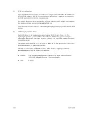
...For the ultra SCSI model, number of connectable SCSI devices on the same SCSI bus is varied as follows. • 8-bit SCSI: 8 drives max. (option for NP model) • 16-bit SCSI: 16 drives max. (4) High speed data transfer Such a high data transfer rate on the SCSI bus is 320... • Arbitration • Disconnection/Reconnection • Data bus parity The SCSI commands can manipulate data through logical block addressing regardless of the physical characteristics of the disk drive. See subsection 5.3.2 for SCSI-2. 8-bit data bus is available only with the large capacity buffer in the...
...For the ultra SCSI model, number of connectable SCSI devices on the same SCSI bus is varied as follows. • 8-bit SCSI: 8 drives max. (option for NP model) • 16-bit SCSI: 16 drives max. (4) High speed data transfer Such a high data transfer rate on the SCSI bus is 320... • Arbitration • Disconnection/Reconnection • Data bus parity The SCSI commands can manipulate data through logical block addressing regardless of the physical characteristics of the disk drive. See subsection 5.3.2 for SCSI-2. 8-bit data bus is available only with the large capacity buffer in the...
Manual/User Guide
Page 21
... You should issue either the SYNCHRONIZE CASHE command or the STOP UNIT command and then confirm that the cashed data is transferred between SCSI bus and disk media through this data buffer. This feature realizes the high speed processing. This feature provides the suitable usage environment...of initiator and the length of data blocks is surely terminated with utilizing high data transfer capability of the SCSI bus regardless of actual data transfer rate of the disk drive. (7) Cache feature After executing the READ command, the IDD reads automatically and stores (prefetches) the ...
... You should issue either the SYNCHRONIZE CASHE command or the STOP UNIT command and then confirm that the cashed data is transferred between SCSI bus and disk media through this data buffer. This feature realizes the high speed processing. This feature provides the suitable usage environment...of initiator and the length of data blocks is surely terminated with utilizing high data transfer capability of the SCSI bus regardless of actual data transfer rate of the disk drive. (7) Cache feature After executing the READ command, the IDD reads automatically and stores (prefetches) the ...
Manual/User Guide
Page 22
... alternate block reassignment If a defective data block is generally 512 bytes at formatting. The drive format is detected during read or write the IDD can be modified from errors in SCSI bus or the disk drive using its alternate data block. (12) Programmable data block length Data can be accessed ...in a physical sequence by these error recovery functions of the drive might increase when the format would be reallocated in...
... alternate block reassignment If a defective data block is generally 512 bytes at formatting. The drive format is detected during read or write the IDD can be modified from errors in SCSI bus or the disk drive using its alternate data block. (12) Programmable data block length Data can be accessed ...in a physical sequence by these error recovery functions of the drive might increase when the format would be reallocated in...
Manual/User Guide
Page 23
.... The disk subsystem with large capacity can be constructed in the good space efficiency. (16) Start/Stop of spindle motor Using the SCSI command, the host system can be used in wide range of environmental conditions. (19) Low noise and low vibration The noise level is...capacity A large capacity can start and stop the spindle motor. (17) Diagnosis The IDD has a diagnostic capability which checks internal controller functions and drive operations to facilitate testing and repair. (18) Low power consumption By using highly integrated LSI components, the power consumption of the IDD is very...
.... The disk subsystem with large capacity can be constructed in the good space efficiency. (16) Start/Stop of spindle motor Using the SCSI command, the host system can be used in wide range of environmental conditions. (19) Low noise and low vibration The noise level is...capacity A large capacity can start and stop the spindle motor. (17) Diagnosis The IDD has a diagnostic capability which checks internal controller functions and drive operations to facilitate testing and repair. (18) Low power consumption By using highly integrated LSI components, the power consumption of the IDD is very...
Manual/User Guide
Page 26
... IC that supports high-speed transmission and an MEEPR4ML (Modified Enhanced Extended Partial Response Class 4 Maximum Likelihood) modulation/demodulation circuit in the vicinity of the SCSI controller. 1-8 C141-E166 Using the movement of the rotating disks, air is attached. (5) Air circulation (recirculation filter, breather filter) The disk enclosure (DE) configures a sealed...
... IC that supports high-speed transmission and an MEEPR4ML (Modified Enhanced Extended Partial Response Class 4 Maximum Likelihood) modulation/demodulation circuit in the vicinity of the SCSI controller. 1-8 C141-E166 Using the movement of the rotating disks, air is attached. (5) Air circulation (recirculation filter, breather filter) The disk enclosure (DE) configures a sealed...
Manual/User Guide
Page 27
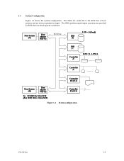
SCSI bus Figure 1.4 System configuration C141-E166 1-9 1.3 System Configuration Figure 1.4 shows the system configuration. The IDDs are connected to the SCSI bus of host systems and are always operated as initiator. The IDDs perform input/output operation as specified by SCSI devices which operate as target.
SCSI bus Figure 1.4 System configuration C141-E166 1-9 1.3 System Configuration Figure 1.4 shows the system configuration. The IDDs are connected to the SCSI bus of host systems and are always operated as initiator. The IDDs perform input/output operation as specified by SCSI devices which operate as target.
Manual/User Guide
Page 28
...NP model, switch selectable) 16-bit SCSI:Selectable from 0 to select the peripheral device for input/output operation. The IDD is constructed so that the whole volume of disk drive is a single logical unit, the selectable number of peripheral device Each SCSI device on which multiple host computers that... operate as initiator or connected through the SCSI bus. For example, the system can be configured as multi...
...NP model, switch selectable) 16-bit SCSI:Selectable from 0 to select the peripheral device for input/output operation. The IDD is constructed so that the whole volume of disk drive is a single logical unit, the selectable number of peripheral device Each SCSI device on which multiple host computers that... operate as initiator or connected through the SCSI bus. For example, the system can be configured as multi...
Manual/User Guide
Page 29
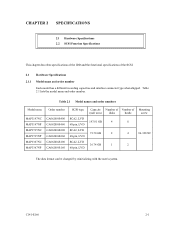
... be changed by reinitializing with the user's system. Table 2.1 Model names and order numbers Model name MAP3147NC MAP3147NP MAP3735NC MAP3735NP MAP3367NC MAP3367NP Order number CA06200-B400 CA06200-B460 CA06200-B200 CA06200-B260 CA06200-B100 CA06200-B160 SCSI type SCA2, LVD 68-pin, LVD SCA2, LVD 68-pin, LVD SCA2, LVD 68-pin...
... be changed by reinitializing with the user's system. Table 2.1 Model names and order numbers Model name MAP3147NC MAP3147NP MAP3735NC MAP3735NP MAP3367NC MAP3367NP Order number CA06200-B400 CA06200-B460 CA06200-B200 CA06200-B260 CA06200-B100 CA06200-B160 SCSI type SCA2, LVD 68-pin, LVD SCA2, LVD 68-pin, LVD SCA2, LVD 68-pin...
Manual/User Guide
Page 30
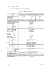
...External dimensions Height: Width: Depth: Weight (max) Power consumption (*5) Fast 5 SCSI MAP3147NC/NP 147.01 GB 4 8 47,908 Specification MAP3735NC/NP 73.50 GB 2 4 47,978 272,896... to 528 byte (Fixed length) SCSI command specification SPI-4 (T10/1365D Rev.7), SAM-2 (T10/1157D Rev.20), SPC-2 (T10/...Number of disks Number of heads Number of cylinders (*2) Formatted capacity/track (B) Number of the IDD. Fast 10 SCSI Inter- Ended face Fast 20 SCSI Cable length: 3 m max Cable length: 3 m max (*6) Cable length: 1.5 m max (*7) LVD U160...
...External dimensions Height: Width: Depth: Weight (max) Power consumption (*5) Fast 5 SCSI MAP3147NC/NP 147.01 GB 4 8 47,908 Specification MAP3735NC/NP 73.50 GB 2 4 47,978 272,896... to 528 byte (Fixed length) SCSI command specification SPI-4 (T10/1365D Rev.7), SAM-2 (T10/1157D Rev.20), SPC-2 (T10/...Number of disks Number of heads Number of cylinders (*2) Formatted capacity/track (B) Number of the IDD. Fast 10 SCSI Inter- Ended face Fast 20 SCSI Cable length: 3 m max Cable length: 3 m max (*6) Cable length: 1.5 m max (*7) LVD U160...
Manual/User Guide
Page 31
(*1) The formatted capacity can be changed by transmission characteristics. (*11) The terminator power pin (SCSI connector) which supplies power to other terminators is not used. The number of user cylinders and alternate cylinders can use cable length of up to 1.5 m. (*8) 1 ... to completely stop from power off or stop command. (*5) This value indicates at ready mode. (*6) Up to 4 SCSI devices having capacitance of 25pF or less can use cable length of up to 3.0 m. (*7) 5 to 8 SCSI devices having capacitance of 25pF or less can be restricted to when the IDD is ready, and the...
(*1) The formatted capacity can be changed by transmission characteristics. (*11) The terminator power pin (SCSI connector) which supplies power to other terminators is not used. The number of user cylinders and alternate cylinders can use cable length of up to 1.5 m. (*8) 1 ... to completely stop from power off or stop command. (*5) This value indicates at ready mode. (*6) Up to 4 SCSI devices having capacitance of 25pF or less can use cable length of up to 3.0 m. (*7) 5 to 8 SCSI devices having capacitance of 25pF or less can be restricted to when the IDD is ready, and the...

