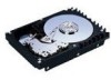
Manual/User Guide
Page 5
... interface connector. Chapter 3 DATA FORMAT This chapter describes the data structure of the disk, the address method, and what to B The appendixes give supplementary information, including a list of setting items and the signal assignments of the above disk drive, and gives the requirements and procedures for setting device number and operation modes, mounting the disk drive, connecting the cables, and confirming drive operation. This chapter also describes diagnostic methods for installing MAP series disk drives. Chapter 7 ERROR...
... interface connector. Chapter 3 DATA FORMAT This chapter describes the data structure of the disk, the address method, and what to B The appendixes give supplementary information, including a list of setting items and the signal assignments of the above disk drive, and gives the requirements and procedures for setting device number and operation modes, mounting the disk drive, connecting the cables, and confirming drive operation. This chapter also describes diagnostic methods for installing MAP series disk drives. Chapter 7 ERROR...
Manual/User Guide
Page 7
... not connect or disconnect cables when power is turned on .(except NC model) C141-E166 v Data loss 1. Make sure that damages to 5 byte) can be performed properly. The DE and LSI become hot during the power is on . • Write protect: CN2 9-10 (NP model only) 3. Do not change the setting of terminals not described 5-5 in each sector where the maximum number of errors (up...
... not connect or disconnect cables when power is turned on .(except NC model) C141-E166 v Data loss 1. Make sure that damages to 5 byte) can be performed properly. The DE and LSI become hot during the power is on . • Write protect: CN2 9-10 (NP model only) 3. Do not change the setting of terminals not described 5-5 in each sector where the maximum number of errors (up...
Manual/User Guide
Page 12
... model only 5-6 5.3.2 Each mode setting (NP model only 5-7 5.3.3 Mode settings ...5-9 5.4 Mounting Drives...5-10 5.4.1 Check before mounting ...5-10 5.4.2 Mounting procedures...5-10 5.5 Connecting Cables...5-11 5.6 Confirming Operations after Installation and Preparation for use 5-12 5.6.1 Confirming initial operations 5-12 5.6.2 Checking SCSI connection 5-13 5.6.3 Formatting ...5-16 5.6.4 Setting parameters ...5-18 5.7 Dismounting Drives...5-22 5.8 Spare Disk Drive ...5-22 CHAPTER 6 DIAGNOSTICS AND MAINTENANCE 6-1 6.1 Diagnostics ...6-1 6.1.1 Self-diagnostics ...6-1 6.1.2 Test programs...
... model only 5-6 5.3.2 Each mode setting (NP model only 5-7 5.3.3 Mode settings ...5-9 5.4 Mounting Drives...5-10 5.4.1 Check before mounting ...5-10 5.4.2 Mounting procedures...5-10 5.5 Connecting Cables...5-11 5.6 Confirming Operations after Installation and Preparation for use 5-12 5.6.1 Confirming initial operations 5-12 5.6.2 Checking SCSI connection 5-13 5.6.3 Formatting ...5-16 5.6.4 Setting parameters ...5-18 5.7 Dismounting Drives...5-22 5.8 Spare Disk Drive ...5-22 CHAPTER 6 DIAGNOSTICS AND MAINTENANCE 6-1 6.1 Diagnostics ...6-1 6.1.1 Self-diagnostics ...6-1 6.1.2 Test programs...
Manual/User Guide
Page 17
... 5.4 Write protect setting (NP model only 5-8 Table 5.5 Setting of the SCSI interface operation mode (NP model only 5-9 Table 5.6 Setting the bus width of the SCSI interface (NP model only 5-9 Table 5.7 Default mode settings (by CHANGE DEFINITION command 5-9 Table 5.8 Setting check list (NP model only 5-10 Table 6.1 Self-diagnostic functions ...6-1 Table 6.2 System-level field troubleshooting 6-14 Table 6.3 Disk drive troubleshooting ...6-15 Table 7.1 Definition of sense data ...7-3 Table A.1 CN2 setting terminal (on NP model drives only A-2 Table B.1 SCSI connector (68 pin type LVD...
... 5.4 Write protect setting (NP model only 5-8 Table 5.5 Setting of the SCSI interface operation mode (NP model only 5-9 Table 5.6 Setting the bus width of the SCSI interface (NP model only 5-9 Table 5.7 Default mode settings (by CHANGE DEFINITION command 5-9 Table 5.8 Setting check list (NP model only 5-10 Table 6.1 Self-diagnostic functions ...6-1 Table 6.2 System-level field troubleshooting 6-14 Table 6.3 Disk drive troubleshooting ...6-15 Table 7.1 Definition of sense data ...7-3 Table A.1 CN2 setting terminal (on NP model drives only A-2 Table B.1 SCSI connector (68 pin type LVD...
Manual/User Guide
Page 30
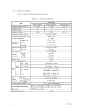
... m max (*9) Data transfer rate (*10) Disk drive SCSI Synchronous mode 64.1 to 479,232 10,025±0.2% 2.99 msec 0.3 ms/0.5 ms 4.5 ms/5.0 ms 10.0 ms/11.0 ms 30 s typ. (60 s max.) 30 s typ. 32/34 MEEPRML 25.4 mm 101.6 mm 146.0 mm 0.75 kg 9.6 W Cable length: 6 m max MAP3367NC/NP 36.74 GB 1 2 48,104 Single- Table 2.2 Function specifications Item Formatted capacity/device (*1) Number of disks Number of heads Number of cylinders (*2) Formatted capacity...
... m max (*9) Data transfer rate (*10) Disk drive SCSI Synchronous mode 64.1 to 479,232 10,025±0.2% 2.99 msec 0.3 ms/0.5 ms 4.5 ms/5.0 ms 10.0 ms/11.0 ms 30 s typ. (60 s max.) 30 s typ. 32/34 MEEPRML 25.4 mm 101.6 mm 146.0 mm 0.75 kg 9.6 W Cable length: 6 m max MAP3367NC/NP 36.74 GB 1 2 48,104 Single- Table 2.2 Function specifications Item Formatted capacity/device (*1) Number of disks Number of heads Number of cylinders (*2) Formatted capacity...
Manual/User Guide
Page 31
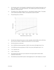
... 512 bytes per sector. (*2) The number of the IDD. (*3) The positioning time is as follows: Seek tim [ms] Seek Difference [2048 Cyl/div] (*4) The start time is the time from power off or stop from power on 1 connection case. (*9) 1 host, 15 devices case. (*10) The maximum data transfer rate may be changed by transmission characteristics. (*11) The terminator power pin (SCSI connector) which supplies power to other terminators is not used. The formatted capacity listed in...
... 512 bytes per sector. (*2) The number of the IDD. (*3) The positioning time is as follows: Seek tim [ms] Seek Difference [2048 Cyl/div] (*4) The start time is the time from power off or stop from power on 1 connection case. (*9) 1 host, 15 devices case. (*10) The maximum data transfer rate may be changed by transmission characteristics. (*11) The terminator power pin (SCSI connector) which supplies power to other terminators is not used. The formatted capacity listed in...
Manual/User Guide
Page 33
... the error rate. CAUTION Data loss For MAP series, Reed Solomon codes are not included in each sector where the maximum number of errors (up to 5 byte) can be corrected. [Total maximum byte: 5 byte × 6 ( interleave) = 30 byte] If the error of read sector keeps allowable error byte number, correction is defined as: MTBF= Operating time (hours) at the drive connector side, during drive ready state. (*6) The terminator power pin (SCSI connector) which supplies power...
... the error rate. CAUTION Data loss For MAP series, Reed Solomon codes are not included in each sector where the maximum number of errors (up to 5 byte) can be corrected. [Total maximum byte: 5 byte × 6 ( interleave) = 30 byte] If the error of read sector keeps allowable error byte number, correction is defined as: MTBF= Operating time (hours) at the drive connector side, during drive ready state. (*6) The terminator power pin (SCSI connector) which supplies power...
Manual/User Guide
Page 34
... trouble, cable failures, or other failures not caused by the equipment are not considered. (2) Mean Time To Repair (MTTR) MTTR is 5 years. Note: The "average DE surface temperature" means the average temperature at the DE surface throughout the year when the IDD is operating. (4) Data security at power failure Integrity of the data on the disk is being performed. The service life is depending on blocks where a write operation...
... trouble, cable failures, or other failures not caused by the equipment are not considered. (2) Mean Time To Repair (MTTR) MTTR is 5 years. Note: The "average DE surface temperature" means the average temperature at the DE surface throughout the year when the IDD is operating. (4) Data security at power failure Integrity of the data on the disk is being performed. The service life is depending on blocks where a write operation...
Manual/User Guide
Page 67
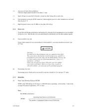
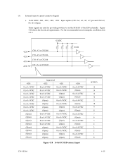
Figure 4.18 16-bit SCSI ID external input C141-E166 4-15 Figure 4.18 shows the electrical requirements. For the recommended circuit examples, see Subsection 4.3.4. (5) External operator panel connector Signals a. 16-bit SCSI -ID3, -ID2, -ID1, -ID0: Input signals (CN1-A1, A3, A5, A7 pin and CN2-02, 04, 06, 08 pin) These signals are used for providing switches to set the SCSI ID of the IDD externally.
Figure 4.18 16-bit SCSI ID external input C141-E166 4-15 Figure 4.18 shows the electrical requirements. For the recommended circuit examples, see Subsection 4.3.4. (5) External operator panel connector Signals a. 16-bit SCSI -ID3, -ID2, -ID1, -ID0: Input signals (CN1-A1, A3, A5, A7 pin and CN2-02, 04, 06, 08 pin) These signals are used for providing switches to set the SCSI ID of the IDD externally.
Manual/User Guide
Page 75
... after turning off the power. b) Do not leave the drive in a dirty or contaminated environment. CHAPTER 5 INSTALLATION 5.1 Notes on Handling Drives 5.2 Connections 5.3 Setting Terminals 5.4 Mounting Drives 5.5 Connecting Cables 5.6 Confirming Operations after Installation and Preparation for Use 5.7 Dismounting Drives 5.8 Spare Disk Drive This chapter describes the notes on Handling Drives The items listed in the specifications in Table 2.1 must be careful when unpacking. CAUTION Hot temperature To prevent injury...
... after turning off the power. b) Do not leave the drive in a dirty or contaminated environment. CHAPTER 5 INSTALLATION 5.1 Notes on Handling Drives 5.2 Connections 5.3 Setting Terminals 5.4 Mounting Drives 5.5 Connecting Cables 5.6 Confirming Operations after Installation and Preparation for Use 5.7 Dismounting Drives 5.8 Spare Disk Drive This chapter describes the notes on Handling Drives The items listed in the specifications in Table 2.1 must be careful when unpacking. CAUTION Hot temperature To prevent injury...
Manual/User Guide
Page 76
... screws. (3) Installation/removal/replacement a) Do not attempt to the PCAs and interface connector when removing the drive from direct shocks. d) Do not remove the sealing label or cover of the package so that the "This Side Up" sign side is recommended to the internal unit when removing cushions. c) Place and keep removed screws and other parts where they are pins 9, 10 (Write Protect) in...
... screws. (3) Installation/removal/replacement a) Do not attempt to the PCAs and interface connector when removing the drive from direct shocks. d) Do not remove the sealing label or cover of the package so that the "This Side Up" sign side is recommended to the internal unit when removing cushions. c) Place and keep removed screws and other parts where they are pins 9, 10 (Write Protect) in...
Manual/User Guide
Page 90
... 6 of SCSI Logical Interface Specifications for each model (part number) when shipped from the default format, all sides of the cable. • Power is formatted with the MODE SELECT or MODE SELECT EXTENDED command. Block descriptor Specify the size (byte length) of data blocks" field. The parameters are connected correctly. • The terminating resistor is mounted on the setting of logical data blocks after initialization is installed in the format parameter (page code = 3) and drive parameter (page code = 4). 5-16...
... 6 of SCSI Logical Interface Specifications for each model (part number) when shipped from the default format, all sides of the cable. • Power is formatted with the MODE SELECT or MODE SELECT EXTENDED command. Block descriptor Specify the size (byte length) of data blocks" field. The parameters are connected correctly. • The terminating resistor is mounted on the setting of logical data blocks after initialization is installed in the format parameter (page code = 3) and drive parameter (page code = 4). 5-16...

Manual/User Guide
Page 92
... executed at installation. 5-18 C141-E166 The model select parameter is not affected. 4. For example, even if the initialization of the disk is performed by the FORMAT UNIT command, the saved value of parameters described in consideration of the MODE SELECT and MODE SELECT EXTENDED commands and specifying the parameters. Refer to Chapter 3 of SCSI Logical Interface Specifications for each parameter 2. This enables the IDD to operate by the user when power is...
... executed at installation. 5-18 C141-E166 The model select parameter is not affected. 4. For example, even if the initialization of the disk is performed by the FORMAT UNIT command, the saved value of parameters described in consideration of the MODE SELECT and MODE SELECT EXTENDED commands and specifying the parameters. Refer to Chapter 3 of SCSI Logical Interface Specifications for each parameter 2. This enables the IDD to operate by the user when power is...
Manual/User Guide
Page 94
...; PER 2. It is recommended to use the default setting in normal operations. (2) Disconnection/reconnection parameters (page code = 2) The following parameters are used to optimize the start timing of reconnection processing to transfer data on the SCSI bus at a read (READ or READ EXTENDED command) or write operation (WRITE, WRITE EXTENDED, or WRITE AND VERIFY command) of the specified values by measuring performance in consideration of the following parameters according to evaluate the validity of...
...; PER 2. It is recommended to use the default setting in normal operations. (2) Disconnection/reconnection parameters (page code = 2) The following parameters are used to optimize the start timing of reconnection processing to transfer data on the SCSI bus at a read (READ or READ EXTENDED command) or write operation (WRITE, WRITE EXTENDED, or WRITE AND VERIFY command) of the specified values by measuring performance in consideration of the following parameters according to evaluate the validity of...
Manual/User Guide
Page 96
... Disabling tagged command queuing Default value 0 (Execution sequence of read/write commands is optimized.) 0 (command is difficult to make sure the spindle motor completely stops after step e). a) Remove the power cable. e) Remove the four mounting screws securing the drive, then remove the drive from the system cabinet. b) Remove the SCSI cable. MC Model uses a single cable for replacement or as a spare. 5-22 C141-E166 c) When the external operator panel is recommended before dismounting the drive to access...
... Disabling tagged command queuing Default value 0 (Execution sequence of read/write commands is optimized.) 0 (command is difficult to make sure the spindle motor completely stops after step e). a) Remove the power cable. e) Remove the four mounting screws securing the drive, then remove the drive from the system cabinet. b) Remove the SCSI cable. MC Model uses a single cable for replacement or as a spare. 5-22 C141-E166 c) When the external operator panel is recommended before dismounting the drive to access...
Manual/User Guide
Page 103
... repair facility for replacing or repairing the disk drive. Fujitsu does not assume responsibility if data is destroyed during servicing or repair. Generally, the following information must be replaced in the field. (3) Parts that can be replaced in the field The PCA cannot be included: a) IDD model, part number (P/N), revision number, serial number (S/N), and date of manufacturing b) Error status • Date when the error occurred • System configuration • Environmental conditions (temperature, humidity, and voltage) c) Error history d) Error...
... repair facility for replacing or repairing the disk drive. Fujitsu does not assume responsibility if data is destroyed during servicing or repair. Generally, the following information must be replaced in the field. (3) Parts that can be replaced in the field The PCA cannot be included: a) IDD model, part number (P/N), revision number, serial number (S/N), and date of manufacturing b) Error status • Date when the error occurred • System configuration • Environmental conditions (temperature, humidity, and voltage) c) Error history d) Error...
Manual/User Guide
Page 110
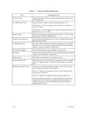
... range (±5%). Check that the +5 VDC value (pins 3 and 4 of the power connector) is 4.75 to -peak value of disk drive) is 11.4 to the hardware and software manuals supplied with the system. 6-14 C141-E166 Check that all disk drives. Check the AC voltage from the power supply. Check that the SCSI interface cable is correctly connected between the disk drive and controller. When possible, execute the system level...
... range (±5%). Check that the +5 VDC value (pins 3 and 4 of the power connector) is 4.75 to -peak value of disk drive) is 11.4 to the hardware and software manuals supplied with the system. 6-14 C141-E166 Check that all disk drives. Check the AC voltage from the power supply. Check that the SCSI interface cable is correctly connected between the disk drive and controller. When possible, execute the system level...
Manual/User Guide
Page 111
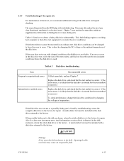
... disk drive is normal but the test method is not faulty. If the disk drive error recurs or a possibly faulty part is incorrect. To check performance, change the disk drive conditions by sense data, and gives supplementary information on finding the error cause (faulty part). C141-E166 6-15 A media defect list must be included with troubleshooting. This is used. Table 6.3 Disk drive troubleshooting Item Frequent or repeated seek errors Intermittent or nonfatal errors...
... disk drive is normal but the test method is not faulty. If the disk drive error recurs or a possibly faulty part is incorrect. To check performance, change the disk drive conditions by sense data, and gives supplementary information on finding the error cause (faulty part). C141-E166 6-15 A media defect list must be included with troubleshooting. This is used. Table 6.3 Disk drive troubleshooting Item Frequent or repeated seek errors Intermittent or nonfatal errors...
Manual/User Guide
Page 124
... faulty part 6-16 format capacity 3-9 format of extended sense data 7-2 format parameter 5-17 FORMAT UNIT command 5-17 formatting 5-16 G gaps 3-8 general description 1-1 general note 5-1 H hardware function test 6-2 hardware structure 1-6 head 1-7 high speed data transfer 1-2 high speed positioning 1-4 I indicating revision number 6-10 indicating revision number at factory shipment 6-9 initial seek operation check 6-12 initial self-diagnostic 6-2 installation 5-1 installation requirement 4-1 installation/removal/replacement 5-2 interface (SCSI bus) test 6-5 internal test...
... faulty part 6-16 format capacity 3-9 format of extended sense data 7-2 format parameter 5-17 FORMAT UNIT command 5-17 formatting 5-16 G gaps 3-8 general description 1-1 general note 5-1 H hardware function test 6-2 hardware structure 1-6 head 1-7 high speed data transfer 1-2 high speed positioning 1-4 I indicating revision number 6-10 indicating revision number at factory shipment 6-9 initial seek operation check 6-12 initial self-diagnostic 6-2 installation 5-1 installation requirement 4-1 installation/removal/replacement 5-2 interface (SCSI bus) test 6-5 internal test...
Manual/User Guide
Page 125
... SCSI function specification 2-7 SCSI ID setting 5-6, 5-7 SCSI interface error 7-4 SCSI standard 1-2 sector format 3-7 seek test 6-2 self-diagnostic 6-1 self-diagnostic function 6-1 SEND DIAGNOSTIC command 6-3 sense data 7-1, 7-4 sense data analysis 7-3 sense key, sense code, and subsense code.......7-1 service clearance area 4-6 service life 6-6 service system and repair 6-7 setting bus width of SCSI interface 5-9 setting check list (NP model only 5-10 setting of SCSI interface operation mode 5-8, 5-9 setting parameter 5-18 setting SCSI terminator power supply 5-7 setting...
... SCSI function specification 2-7 SCSI ID setting 5-6, 5-7 SCSI interface error 7-4 SCSI standard 1-2 sector format 3-7 seek test 6-2 self-diagnostic 6-1 self-diagnostic function 6-1 SEND DIAGNOSTIC command 6-3 sense data 7-1, 7-4 sense data analysis 7-3 sense key, sense code, and subsense code.......7-1 service clearance area 4-6 service life 6-6 service system and repair 6-7 setting bus width of SCSI interface 5-9 setting check list (NP model only 5-10 setting of SCSI interface operation mode 5-8, 5-9 setting parameter 5-18 setting SCSI terminator power supply 5-7 setting...


