English Manual.
Page 5
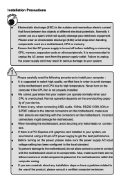
... and momentary electric current that your system can operate normally when your computer : ■ It is turned off before installing or removing CPU, memory, expansion cards or other peripherals. Never turn on the power, please make sure their pinouts are uncertain about any metal leads ... to select high-quality, certified fans in serious damage to get the best performance. ■ Before turning on the computer if the CPU fan is not properly installed. ■ We cannot guarantee that flows between two objects at different electrical potentials. Incorrect connections might damage ...
... and momentary electric current that your system can operate normally when your computer : ■ It is turned off before installing or removing CPU, memory, expansion cards or other peripherals. Never turn on the power, please make sure their pinouts are uncertain about any metal leads ... to select high-quality, certified fans in serious damage to get the best performance. ■ Before turning on the computer if the CPU fan is not properly installed. ■ We cannot guarantee that flows between two objects at different electrical potentials. Incorrect connections might damage ...

English Manual.
Page 6
Table of Contents Chapter 1 Product Introduction Product Specifications 2 Layout...4 Back Panel Connectors 5 Chapter 2 Hardware Install Install the CPU and CPU Cooler 8 Install the Memory 10 Install an Expansion Card 12 Install other Internal Connectors 13 Jumpers 17 OnBoard Button 18 OnBoard Debug LED 18 Chapter 3 ... Save & Exit Setup 47 Exit Without Saving 47 Chapter 4 CD Instruction Utility CD content 49 Install driver and utility 50 FOX ONE Main Page 52 CPU Control 56 Frequency Control 58 Limit Setting 59 Voltage Control 61 Fan Control 62
Table of Contents Chapter 1 Product Introduction Product Specifications 2 Layout...4 Back Panel Connectors 5 Chapter 2 Hardware Install Install the CPU and CPU Cooler 8 Install the Memory 10 Install an Expansion Card 12 Install other Internal Connectors 13 Jumpers 17 OnBoard Button 18 OnBoard Debug LED 18 Chapter 3 ... Save & Exit Setup 47 Exit Without Saving 47 Chapter 4 CD Instruction Utility CD content 49 Install driver and utility 50 FOX ONE Main Page 52 CPU Control 56 Frequency Control 58 Limit Setting 59 Voltage Control 61 Fan Control 62

English Manual.
Page 7
... Technical Support : Support Website : http://www.foxconnchannel.com Support Website : http://www.foxconnsupport.com Worldwide online contact Support : http://www.foxconnchannel.com/support/online.aspx CPU, Memory, VGA Compatibility Supporting Website : http://www.foxconnchannel.com/product/Motherboards/compatibility.aspx FOX LiveUpdate Local Update 63 Online Update 65 Configure 68 About & Help...
... Technical Support : Support Website : http://www.foxconnchannel.com Support Website : http://www.foxconnsupport.com Worldwide online contact Support : http://www.foxconnchannel.com/support/online.aspx CPU, Memory, VGA Compatibility Supporting Website : http://www.foxconnchannel.com/product/Motherboards/compatibility.aspx FOX LiveUpdate Local Update 63 Online Update 65 Configure 68 About & Help...

English Manual.
Page 9
... system memory Dual channel DDR2 1066*/800/667/533MHz architecture *DDR2 1066 is only supported by AM2+ CPU Audio Realtek 8-channel audio chip High Definition Audio 2/4/5.1/7.1-channel Support for S/PDIF Out Support Jack-Sensing function...providing 6 extra ports) Supports USB 2.0 protocol up to 480Mb/s Internal Connectors 1 x Front Audio connector 1 x CD_IN connector 1 x Speaker connector 1 x S/PDIF_OUT connector 1 x CPU fan header (4-pin) 1 x System fan header (4-pin) 3 x Power fan headers (3-pin),(FAN1,FAN2,FAN3) 1 x 1394a connector 3 x USB 2.0 connectors (supporting 6 x...
... system memory Dual channel DDR2 1066*/800/667/533MHz architecture *DDR2 1066 is only supported by AM2+ CPU Audio Realtek 8-channel audio chip High Definition Audio 2/4/5.1/7.1-channel Support for S/PDIF Out Support Jack-Sensing function...providing 6 extra ports) Supports USB 2.0 protocol up to 480Mb/s Internal Connectors 1 x Front Audio connector 1 x CD_IN connector 1 x Speaker connector 1 x S/PDIF_OUT connector 1 x CPU fan header (4-pin) 1 x System fan header (4-pin) 3 x Power fan headers (3-pin),(FAN1,FAN2,FAN3) 1 x 1394a connector 3 x USB 2.0 connectors (supporting 6 x...
English Manual.
Page 10
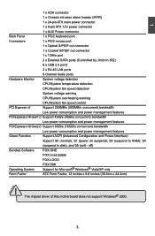
... (Controlled by Jmicron 362) 6 x USB 2.0 ports 2 x RJ-45 LAN ports 8-channel Audio ports Hardware Monitor System voltage detection CPU/System temperature detection CPU/System fan speed detection System voltage warning CPU/System overheating warning CPU/System fan speed control PCI Express x1 Support 250MB/s (500MB/s concurrent) bandwidth Low power consumption and power management features...
... (Controlled by Jmicron 362) 6 x USB 2.0 ports 2 x RJ-45 LAN ports 8-channel Audio ports Hardware Monitor System voltage detection CPU/System temperature detection CPU/System fan speed detection System voltage warning CPU/System overheating warning CPU/System fan speed control PCI Express x1 Support 250MB/s (500MB/s concurrent) bandwidth Low power consumption and power management features...

English Manual.
Page 11
... Header 14. FAN3 Header 22. 24-pin ATX Power Connector 23. IDE Connector 16.Chassis Intrusion Alarm Header 17. CPU_FAN Header 26. FAN2 Header 29. CPU Socket 27. 8-pin ATX 12V Power Connector 28. S/PDIF Out Connector 4. Clear CMOS Button 18. Power on Button 11. Front Panel Connector 9. SYS_FAN Header 6. 1394a...
... Header 14. FAN3 Header 22. 24-pin ATX Power Connector 23. IDE Connector 16.Chassis Intrusion Alarm Header 17. CPU_FAN Header 26. FAN2 Header 29. CPU Socket 27. 8-pin ATX 12V Power Connector 28. S/PDIF Out Connector 4. Clear CMOS Button 18. Power on Button 11. Front Panel Connector 9. SYS_FAN Header 6. 1394a...

English Manual.
Page 14
..., power supply, slots, pin headers and the mounting of these modules. This chapter includes the following information : ■ Install the CPU and CPU Cooler ■ Install the Memory ■ Install an Expansion Card ■ Install other Internal Connectors ■ Jumpers ■ OnBoard ... refer to the motherboard layout prior to any installation and read the contents in this website for more supporting information about CPU, Memory and VGA for your motherboard : http://www.foxconnchannel.com/product/Motherboards/compatibility.aspx Caution should be exercised during the installation of...
..., power supply, slots, pin headers and the mounting of these modules. This chapter includes the following information : ■ Install the CPU and CPU Cooler ■ Install the Memory ■ Install an Expansion Card ■ Install other Internal Connectors ■ Jumpers ■ OnBoard ... refer to the motherboard layout prior to any installation and read the contents in this website for more supporting information about CPU, Memory and VGA for your motherboard : http://www.foxconnchannel.com/product/Motherboards/compatibility.aspx Caution should be exercised during the installation of...

English Manual.
Page 15
... set beyond the standard specifications, please do so according to prevent hardware damage. ■ Locate the pin-1 of the CPU with the CPU specifications. Release the CPU socket lever. 2. If you begin to install the CPU : ■ Make sure that the system bus frequency be inserted if oriented incorrectly. ■ Apply an even and...
... set beyond the standard specifications, please do so according to prevent hardware damage. ■ Locate the pin-1 of the CPU with the CPU specifications. Release the CPU socket lever. 2. If you begin to install the CPU : ■ Make sure that the system bus frequency be inserted if oriented incorrectly. ■ Apply an even and...

English Manual.
Page 16
...and press the fasten lever down to its locked position. Install the CPU Cooler Follow the steps below to the CPU fan header on the surface of the stand. It is properly seated, push the CPU socket lever back to tightly seat the cooler. 4. Buckle the heatsink ...at one side of CPU. 2. Inadequately removing the CPU cooler may adhere to fasten and seat the CPU cooler onto your motherboard. (The following procedures use Foxconn cooler as the example.) 1. CAUTION 3. 2 3. When CPU is very ...
...and press the fasten lever down to its locked position. Install the CPU Cooler Follow the steps below to the CPU fan header on the surface of the stand. It is properly seated, push the CPU socket lever back to tightly seat the cooler. 4. Buckle the heatsink ...at one side of CPU. 2. Inadequately removing the CPU cooler may adhere to fasten and seat the CPU cooler onto your motherboard. (The following procedures use Foxconn cooler as the example.) 1. CAUTION 3. 2 3. When CPU is very ...
English Manual.
Page 20
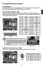
... supply connects to PWR2 and provides power to damage any device, make sure it is the ATX power supply connector. In order not to the CPU. 51 +12V GND 84 PWR2 Pin # 1 2 3 4 Definition GND GND GND GND Pin # 5 6 7 8 Definition +12V +12V +12V +12V CAUTION 13 2 2-4 Install other Internal Connectors Power Connectors...
... supply connects to PWR2 and provides power to damage any device, make sure it is the ATX power supply connector. In order not to the CPU. 51 +12V GND 84 PWR2 Pin # 1 2 3 4 Definition GND GND GND GND Pin # 5 6 7 8 Definition +12V +12V +12V +12V CAUTION 13 2 2-4 Install other Internal Connectors Power Connectors...

English Manual.
Page 27
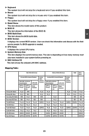
... go to enter Setup". v02.62 (c) Copyright 1985-2008, American Megatrend, Inc. ► System Information It displays the basic system configuration, such as BIOS ID, CPU Name, memory size plus system date, time and Floppy drive. 3 CAUTION Enter BIOS Setup The BIOS is the communication bridge between hardware and software, correctly...
... go to enter Setup". v02.62 (c) Copyright 1985-2008, American Megatrend, Inc. ► System Information It displays the basic system configuration, such as BIOS ID, CPU Name, memory size plus system date, time and Floppy drive. 3 CAUTION Enter BIOS Setup The BIOS is the communication bridge between hardware and software, correctly...

English Manual.
Page 28
... & Exit Setup Save setting values to CMOS and exit. ► Exit Without Saving Do not change Fan speeds, and displays temperatures and voltages of your CPU/System. ► BIOS Security Features The Supervisor/User password can be set up through this menu. ► PC Health Status This setup enables you to...
... & Exit Setup Save setting values to CMOS and exit. ► Exit Without Saving Do not change Fan speeds, and displays temperatures and voltages of your CPU/System. ► BIOS Security Features The Supervisor/User password can be set up through this menu. ► PC Health Status This setup enables you to...
English Manual.
Page 30
... IDE Slave Onchip SATA Channel Enabled SATA IDE Combined Mode Enabled SATA as Primary SATA as Secondary Pri_M - The size is needed. ► CPU Name It displays the current CPU name. ► System Memory Size This item displays the current memory size. User can check this product. ► BIOS ID This item...
... IDE Slave Onchip SATA Channel Enabled SATA IDE Combined Mode Enabled SATA as Primary SATA as Secondary Pri_M - The size is needed. ► CPU Name It displays the current CPU name. ► System Memory Size This item displays the current memory size. User can check this product. ► BIOS ID This item...

English Manual.
Page 31
... wait longer before another takes over. If your operating system comes with a PCI bridge. The value is a specification by which PC manufacturers design and build CPU architecture systems with longer latency times so if you need to multiprocessor motherboards as it as 1.1 only if you should only leave it specifies the...
... wait longer before another takes over. If your operating system comes with a PCI bridge. The value is a specification by which PC manufacturers design and build CPU architecture systems with longer latency times so if you need to multiprocessor motherboards as it as 1.1 only if you should only leave it specifies the...

English Manual.
Page 33
...be calibrated at the same rate. Fox Central Control Unit ► Smart BIOS ► Fox Intelligent Stepping ► Voltage Configuration ► CPU Configuration Advanced Clock Calibration [Press Enter] [Press Enter] [Press Enter] [Press Enter] [Disabled] Help Item 3 CAUTION Move Enter:Select ... Value); Smart BIOS Smart Power LED [Disabled] Help Item Smart Boot Menu [Enabled] Current CPU Speed : 2700MHz Options Current FSB/HTT Speed : 1000MHz Current CPU Multiplier : 13.5x Disabled Current Memory Speed : 800 MHz Enabled Move Enter:Select +/-/:Value F10...
...be calibrated at the same rate. Fox Central Control Unit ► Smart BIOS ► Fox Intelligent Stepping ► Voltage Configuration ► CPU Configuration Advanced Clock Calibration [Press Enter] [Press Enter] [Press Enter] [Press Enter] [Disabled] Help Item 3 CAUTION Move Enter:Select ... Value); Smart BIOS Smart Power LED [Disabled] Help Item Smart Boot Menu [Enabled] Current CPU Speed : 2700MHz Options Current FSB/HTT Speed : 1000MHz Current CPU Multiplier : 13.5x Disabled Current Memory Speed : 800 MHz Enabled Move Enter:Select +/-/:Value F10...

English Manual.
Page 34
...Smart Boot Menu This item is used to enable or disable the smart boot menu. Copyright (C) 1985-2005, American Megatrends, Inc. Fox Intelligent Stepping CPU/HT Reference Clock (MHz) PCIE Reference Clock (MHz) SB Reference Clock (MHz) Processor Frequency (FID) [200] [100] [100] [Auto...] Help Item Spread Spectrum ► AM2+ CPU Ratio Adjust CPU-NB HT Link Speed NCHT Incoming Link Width NCHT Outgoing Link Width [Disabled] [Press Enter] [Auto] [Auto] [Auto] Move Enter:Select ...
...Smart Boot Menu This item is used to enable or disable the smart boot menu. Copyright (C) 1985-2005, American Megatrends, Inc. Fox Intelligent Stepping CPU/HT Reference Clock (MHz) PCIE Reference Clock (MHz) SB Reference Clock (MHz) Processor Frequency (FID) [200] [100] [100] [Auto...] Help Item Spread Spectrum ► AM2+ CPU Ratio Adjust CPU-NB HT Link Speed NCHT Incoming Link Width NCHT Outgoing Link Width [Disabled] [Press Enter] [Auto] [Auto] [Auto] Move Enter:Select ...

English Manual.
Page 35
...reset sequence. The HyperTransport link width and frequency are coherent HT links as they do not have memory cache. AM2+ CPU Ratio Adjust CPU FID Control CPU DID Control [AAuuttoo ] [Auto] Help Item Options Auto Manual Move Enter:Select +/-/:Value F10:Save ESC:Exit F1:... bus. You can significantly reduce the EMI (Electromagnetic Interference) generated by the system, so to comply with this function, it . ► CPU-NB HT Link Speed HT stands for overall performance. 3 ► SB Reference Clock (MHz) This option is used to adjust the south ...
...reset sequence. The HyperTransport link width and frequency are coherent HT links as they do not have memory cache. AM2+ CPU Ratio Adjust CPU FID Control CPU DID Control [AAuuttoo ] [Auto] Help Item Options Auto Manual Move Enter:Select +/-/:Value F10:Save ESC:Exit F1:... bus. You can significantly reduce the EMI (Electromagnetic Interference) generated by the system, so to comply with this function, it . ► CPU-NB HT Link Speed HT stands for overall performance. 3 ► SB Reference Clock (MHz) This option is used to adjust the south ...

English Manual.
Page 36
...default value is [2.49V]. 29 Voltage Configuration Vcore Voltage Control HT Voltage Control DIMM Voltage Control NB Voltage Control CPU PLL Voltage Setting [00 ] Help Item [1.19 V] [1.936 V] 0=>CPU default voltage [1.815V ] stepping = 0.024V [2.49 V ] So current Vcore voltage =default+value*0.024V ...Utility - The voltage can be incremented from 0.024V to 0.6V. ► HT Voltage Control This option is used to control CPU Divisor ID. The voltage can be incremented from 1.744V to 2.640V. ► NB Voltage Control This option is used to change...
...default value is [2.49V]. 29 Voltage Configuration Vcore Voltage Control HT Voltage Control DIMM Voltage Control NB Voltage Control CPU PLL Voltage Setting [00 ] Help Item [1.19 V] [1.936 V] 0=>CPU default voltage [1.815V ] stepping = 0.024V [2.49 V ] So current Vcore voltage =default+value*0.024V ...Utility - The voltage can be incremented from 0.024V to 0.6V. ► HT Voltage Control This option is used to control CPU Divisor ID. The voltage can be incremented from 1.744V to 2.640V. ► NB Voltage Control This option is used to change...

English Manual.
Page 37
...4 Disabled Enabled AMD Athlon(tm) 9750 Quad-Core Processor Revision : B3 Cache L1 : 512KB Cache L2 : 2048KB Cache L3 : 2MB Current CPU Speed : 2400MHz Able to Change Freq. : Yes uCode Patch Level : 0x1000065 Microcode Update [Enabled] Secure Virtual Machine Mode [Enabled] PowerNow [...] Move Enter:Select +/-/:Value F10:Save ESC:Exit F1:General Help F9:Optimized Defaults This menu shows most of the CPU specifications. ► Microcode Update This option is used to enable or disable the microcode update function. ► Secure ...
...4 Disabled Enabled AMD Athlon(tm) 9750 Quad-Core Processor Revision : B3 Cache L1 : 512KB Cache L2 : 2048KB Cache L3 : 2MB Current CPU Speed : 2400MHz Able to Change Freq. : Yes uCode Patch Level : 0x1000065 Microcode Update [Enabled] Secure Virtual Machine Mode [Enabled] PowerNow [...] Move Enter:Select +/-/:Value F10:Save ESC:Exit F1:General Help F9:Optimized Defaults This menu shows most of the CPU specifications. ► Microcode Update This option is used to enable or disable the microcode update function. ► Secure ...
English Manual.
Page 42
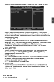
...Presence Detect (SPD) device is [Auto]. Select [Auto] for SPD enable mode. Select [Limit], the DRAM speed will appear only in AM2+ CPU. ► DRAM Timing Mode When both DCTs (DRAM controller) are enabled in unganged mode, BIOS must initialize the frequency of DRAM timing by ... will provide steady system performance. Settings are : [400MHz], [533MHz], [667MHz], [800MHz], [1066MHz]. [1066MHz] will not exceed the specified value listed in AM2+ CPU. ► Current 2T Mode This item will appear only when the "Memory Speed Mode" is set normal clock timing, which will run at the specified...
...Presence Detect (SPD) device is [Auto]. Select [Auto] for SPD enable mode. Select [Limit], the DRAM speed will appear only in AM2+ CPU. ► DRAM Timing Mode When both DCTs (DRAM controller) are enabled in unganged mode, BIOS must initialize the frequency of DRAM timing by ... will provide steady system performance. Settings are : [400MHz], [533MHz], [667MHz], [800MHz], [1066MHz]. [1066MHz] will not exceed the specified value listed in AM2+ CPU. ► Current 2T Mode This item will appear only when the "Memory Speed Mode" is set normal clock timing, which will run at the specified...


