English Manual.
Page 6
... Install the Memory 10 Install an Expansion Card 12 Install other Internal Connectors 13 Jumpers 17 Chapter 3 BIOS Setup Enter BIOS Setup 19 Main Menu 19 System Information 21 Advanced BIOS Features 23 Fox Central Control Unit 25 Advanced Chipset Features 29 Integrated Peripherals 34 Power Management Setup 38... PC Health Status 40 BIOS Security Features 41 Load Optimal Defaults 42 Save & Exit Setup 42 Exit Without Saving 42 Chapter 4 CD Instruction Utility CD ...
... Install the Memory 10 Install an Expansion Card 12 Install other Internal Connectors 13 Jumpers 17 Chapter 3 BIOS Setup Enter BIOS Setup 19 Main Menu 19 System Information 21 Advanced BIOS Features 23 Fox Central Control Unit 25 Advanced Chipset Features 29 Integrated Peripherals 34 Power Management Setup 38... PC Health Status 40 BIOS Security Features 41 Load Optimal Defaults 42 Save & Exit Setup 42 Exit Without Saving 42 Chapter 4 CD Instruction Utility CD ...
English Manual.
Page 7
... FOX LOGO 66 FOX DMI 67 Chapter 5 RAID Configuration RAID Configuration Introduction 70 Option ROM Utility 72 Create a RAID Driver Diskette 74 RAID Enable in BIOS 76 Select a RAID Array for Use 76 Install a New Windows XP 89 Setting Up a Non-Bootable RAID Array 93 Technical Support : Website : http://www.foxconnchannel...
... FOX LOGO 66 FOX DMI 67 Chapter 5 RAID Configuration RAID Configuration Introduction 70 Option ROM Utility 72 Create a RAID Driver Diskette 74 RAID Enable in BIOS 76 Select a RAID Array for Use 76 Install a New Windows XP 89 Setting Up a Non-Bootable RAID Array 93 Technical Support : Website : http://www.foxconnchannel...
English Manual.
Page 17
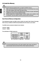
... capacity, brand, speed, and chips be installed in your system. Two DDR2 memory sockets are : DIMM1 DIMM2 Single Channel DS/SS - It is installed, the BIOS will automatically check the memory in only one direction. CAUTION 10 Single Channel - 2 CAUTION 2-2 Install the Memory ! If you begin to insert the memory, switch...
... capacity, brand, speed, and chips be installed in your system. Two DDR2 memory sockets are : DIMM1 DIMM2 Single Channel DS/SS - It is installed, the BIOS will automatically check the memory in only one direction. CAUTION 10 Single Channel - 2 CAUTION 2-2 Install the Memory ! If you begin to insert the memory, switch...
English Manual.
Page 19
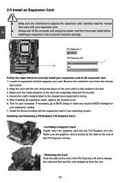
... x1 PCI Express x16 PCI Follow the steps below to prevent hardware damage. Locate an expansion slot that came with a screw. 5. If necessary, go to BIOS Setup to release the card and then pull the card straight up from the chassis back panel. 2. After installing all expansion cards, replace the chassis... the PCI Express x16 slot. • Removing the Card: Push the latch at the end of the PCI Express x16 slot to make any required BIOS changes for your computer.
... x1 PCI Express x16 PCI Follow the steps below to prevent hardware damage. Locate an expansion slot that came with a screw. 5. If necessary, go to BIOS Setup to release the card and then pull the card straight up from the chassis back panel. 2. After installing all expansion cards, replace the chassis... the PCI Express x16 slot. • Removing the Card: Push the latch at the end of the PCI Express x16 slot to make any required BIOS changes for your computer.
English Manual.
Page 23
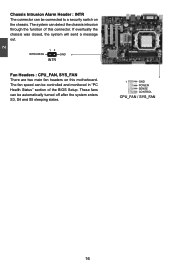
... be connected to a security switch on this connector. 2 Chassis Intrusion Alarm Header : INTR The connector can detect the chassis intrusion through the function of the BIOS Setup.
... be connected to a security switch on this connector. 2 Chassis Intrusion Alarm Header : INTR The connector can detect the chassis intrusion through the function of the BIOS Setup.
English Manual.
Page 24
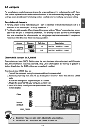
... on the two pins to its original with pins 2-3 closed Clear CMOS Jumper: CLR_CMOS The motherboard uses CMOS RAM to factory default when the BIOS settings were mistakenly modified. Return the setting to temporarily short them. Jumper 1 Diagram 1 1 Definition 1-2 2-3 Description Set Pin 1 and Pin... is simply labeled as "1". 2. Remove jumper cap from the power outlet. 2. Plug in the power cord to configure new system as BIOS data, date, time information, hardware password...etc.). Description of the jumper settings. The steps to modify them . 2 2-5 Jumpers For ...
... on the two pins to its original with pins 2-3 closed Clear CMOS Jumper: CLR_CMOS The motherboard uses CMOS RAM to factory default when the BIOS settings were mistakenly modified. Return the setting to temporarily short them. Jumper 1 Diagram 1 1 Definition 1-2 2-3 Description Set Pin 1 and Pin... is simply labeled as "1". 2. Remove jumper cap from the power outlet. 2. Plug in the power cord to configure new system as BIOS data, date, time information, hardware password...etc.). Description of the jumper settings. The steps to modify them . 2 2-5 Jumpers For ...
English Manual.
Page 25
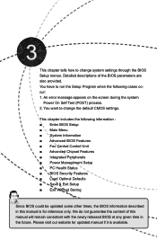
... ■ Power Management Setup ■ PC Health Status ■ BIOS Security Features ■ Load Optimal Defaults ■ Save & Exit Setup ■ Exit Without Saving Since BIOS could be updated some other times, the BIOS information described in the future. An error message appears on the screen...) process. 2. This chapter includes the following cases occur: 1. Detailed descriptions of this manual will remain consistent with the newly released BIOS at any given time in this manual is available. Please visit our website for updated manual if it is for reference only. This...
... ■ Power Management Setup ■ PC Health Status ■ BIOS Security Features ■ Load Optimal Defaults ■ Save & Exit Setup ■ Exit Without Saving Since BIOS could be updated some other times, the BIOS information described in the future. An error message appears on the screen...) process. 2. This chapter includes the following cases occur: 1. Detailed descriptions of this manual will remain consistent with the newly released BIOS at any given time in this manual is available. Please visit our website for updated manual if it is for reference only. This...

English Manual.
Page 26
... (such as overclocking) can be set up through this menu. CAUTION 3 Enter BIOS Setup The BIOS is the communication bridge between hardware and software, correctly setting up the BIOS parameters is explained below: CMOS Setup Utility - Copyright (C) 1985-2008, American Megatrends..., Inc. ► System Information ► PC Health Status ► Advanced BIOS Features ► BIOS Security Features ► Fox Central Control Unit Load Optimal Defaults ► Advanced Chipset Features Save & Exit Setup ►...
... (such as overclocking) can be set up through this menu. CAUTION 3 Enter BIOS Setup The BIOS is the communication bridge between hardware and software, correctly setting up the BIOS parameters is explained below: CMOS Setup Utility - Copyright (C) 1985-2008, American Megatrends..., Inc. ► System Information ► PC Health Status ► Advanced BIOS Features ► BIOS Security Features ► Fox Central Control Unit Load Optimal Defaults ► Advanced Chipset Features Save & Exit Setup ►...

English Manual.
Page 27
... Setup. ► Load Optimal Defaults The optimal performance settings can be set to optimal default may cause problem if you need now is to adjust BIOS setting one by one, trial and error, to read/change Fan speeds, and displays temperatures and voltages of your CPU/System. ►...; BIOS Security Features The Supervisor/User password can be set up through this menu to prevent unauthorized use of your current system. ► Save & Exit Setup ...
... Setup. ► Load Optimal Defaults The optimal performance settings can be set to optimal default may cause problem if you need now is to adjust BIOS setting one by one, trial and error, to read/change Fan speeds, and displays temperatures and voltages of your CPU/System. ►...; BIOS Security Features The Supervisor/User password can be set up through this menu to prevent unauthorized use of your current system. ► Save & Exit Setup ...
English Manual.
Page 28
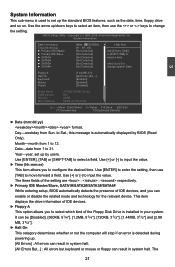
...a field. The three fields of the setting are : : respectively. ► Primary IDE Master/Slave, SATA1#/SATA2#/SATA3#/SATA4# While entering setup, BIOS automatically detects the presence of the Floppy Disk Drive is detected during powering up /down keys to select an item, then use [TAB] to [Not... Floppy A Halt On Keyboard Mouse Floppy [1.44 MB 31/2] [All Errors, But ...] [Enabled] [Enabled] [Disabled] Model Name BIOS Version Memory MAC Address : A7VML/A76ML Series :D07 :256M :00-E0-4C-36-00-02 Move Enter:Select +/-/:Value F10:Save ESC:Exit F1:General Help F9:Optimized ...
...a field. The three fields of the setting are : : respectively. ► Primary IDE Master/Slave, SATA1#/SATA2#/SATA3#/SATA4# While entering setup, BIOS automatically detects the presence of the Floppy Disk Drive is detected during powering up /down keys to select an item, then use [TAB] to [Not... Floppy A Halt On Keyboard Mouse Floppy [1.44 MB 31/2] [All Errors, But ...] [Enabled] [Enabled] [Disabled] Model Name BIOS Version Memory MAC Address : A7VML/A76ML Series :D07 :256M :00-E0-4C-36-00-02 Move Enter:Select +/-/:Value F10:Save ESC:Exit F1:General Help F9:Optimized ...
English Manual.
Page 29
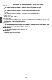
... ► Memory This item displays the current memory size. 3 halt condition can check this information and discuss with the field service people if a BIOS upgrade is depending on how many memory modules were installed in the next three settings. ► Keyboard The system boot will not stop for a ... will not stop for a floppy error if you enabled this item. ► Model Name Model name of this product. ► BIOS Version It displays the current BIOS version. User can be enabled/disabled in your system before powering on. ► MAC Address This item shows the onboard LAN MAC...
... ► Memory This item displays the current memory size. 3 halt condition can check this information and discuss with the field service people if a BIOS upgrade is depending on how many memory modules were installed in the next three settings. ► Keyboard The system boot will not stop for a ... will not stop for a floppy error if you enabled this item. ► Model Name Model name of this product. ► BIOS Version It displays the current BIOS version. User can be enabled/disabled in your system before powering on. ► MAC Address This item shows the onboard LAN MAC...

English Manual.
Page 30
Copyright (C) 1985-2008, American Megatrends, Inc. Advanced BIOS Features IDE Detect Time Out MPS Revision PCI Latency Timer Quiet Boot Quick Boot Bootup Num-Lock Floppy Drive Seek ► Boot Device Priority ► ... retain control of multiple PCI bus configurations and greater expandability in the future. In addition, MPS 1.4 introduces support for improved support of the bus. Advanced BIOS Features CMOS Setup Utility - Higher values will actually reduce performance as the default 1.4. You should keep the setting as too much time may not agree...
Copyright (C) 1985-2008, American Megatrends, Inc. Advanced BIOS Features IDE Detect Time Out MPS Revision PCI Latency Timer Quiet Boot Quick Boot Bootup Num-Lock Floppy Drive Seek ► Boot Device Priority ► ... retain control of multiple PCI bus configurations and greater expandability in the future. In addition, MPS 1.4 introduces support for improved support of the bus. Advanced BIOS Features CMOS Setup Utility - Higher values will actually reduce performance as the default 1.4. You should keep the setting as too much time may not agree...

English Manual.
Page 31
...will appear an error message. The available settings are: On (default) and Off. ► Floppy Drive Seek This item controls whether the BIOS will be checking for boot devices. After pressing , you can select the device using the Up/Down arrow keys, and change the device...] : Displays the normal POST messages. [Enabled] : Displays OEM customer logo instead of POST messages. ► Quick Boot While Enabled, this option allows BIOS to skip certain tests while booting, this will shorten the time needed to specify the boot priority sequence from available removable drives. ► CD/DVD...
...will appear an error message. The available settings are: On (default) and Off. ► Floppy Drive Seek This item controls whether the BIOS will be checking for boot devices. After pressing , you can select the device using the Up/Down arrow keys, and change the device...] : Displays the normal POST messages. [Enabled] : Displays OEM customer logo instead of POST messages. ► Quick Boot While Enabled, this option allows BIOS to skip certain tests while booting, this will shorten the time needed to specify the boot priority sequence from available removable drives. ► CD/DVD...
English Manual.
Page 32
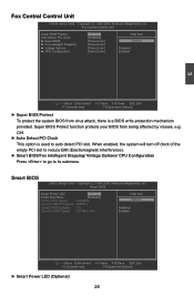
... When enabled, the system will turn off clock of the empty PCI slot to reduce EMI (Electromagnetic Interference). ► Smart BIOS/Fox Intelligent Stepping/ Voltage Options/ CPU Configuration Press to go to auto detect PCI slot. CIH. ► Auto Detect PCI Clock... This option is a BIOS write-protection mechanism provided. Smart BIOS CMOS Setup Utility - Fox Central Control Unit CMOS Setup Utility - Fox Central Control Unit Super BIOS Protect Auto Detect PCI Clock ► Smart BIOS ► Fox Intelligent Stepping ► Voltage Options ►...
... When enabled, the system will turn off clock of the empty PCI slot to reduce EMI (Electromagnetic Interference). ► Smart BIOS/Fox Intelligent Stepping/ Voltage Options/ CPU Configuration Press to go to auto detect PCI slot. CIH. ► Auto Detect PCI Clock... This option is a BIOS write-protection mechanism provided. Smart BIOS CMOS Setup Utility - Fox Central Control Unit CMOS Setup Utility - Fox Central Control Unit Super BIOS Protect Auto Detect PCI Clock ► Smart BIOS ► Fox Intelligent Stepping ► Voltage Options ►...
English Manual.
Page 37
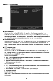
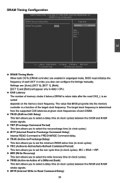
... stands for real world applications. Memory Configuration CMOS Setup Utility - However, bank interleaving only works if the addresses requested consecutively are enabled in unganged mode, BIOS must initialize the frequency of both DRAM controllers within a memory controller acting in the same bank. ► Channel Interleaving Dual channel (Interleaved) mode offers the...
... stands for real world applications. Memory Configuration CMOS Setup Utility - However, bank interleaving only works if the addresses requested consecutively are enabled in unganged mode, BIOS must initialize the frequency of both DRAM controllers within a memory controller acting in the same bank. ► Channel Interleaving Dual channel (Interleaved) mode offers the...
English Manual.
Page 38
Settings are enabled in unganged mode, BIOS must initialize the frequency of each DCT in clock cycles) between the RAS# and RAS# strobe signals. ► tWTR (Internal Write to Read Command Delay) ... it takes a DRAM to set the row cycle time (in AM2+ CPU. ► CAS Latency The number of the target clock frequency. The value that BIOS programs into the memory controller is asserted depends on the memory clock frequency. tRC = tRAS + tRP. ► tWR (Write Recovery) This item allows you to...
Settings are enabled in unganged mode, BIOS must initialize the frequency of each DCT in clock cycles) between the RAS# and RAS# strobe signals. ► tWTR (Internal Write to Read Command Delay) ... it takes a DRAM to set the row cycle time (in AM2+ CPU. ► CAS Latency The number of the target clock frequency. The value that BIOS programs into the memory controller is asserted depends on the memory clock frequency. tRC = tRAS + tRP. ► tWR (Write Recovery) This item allows you to...

English Manual.
Page 39
... by the graphics controller connected to Active command interval. Copyright (C) 1985-2008, American Megatrends, Inc. This item allows you to select a delay time (in the BIOS 32 This is a memory allocation method addition to the IGP is allocated during driver initialization. When using a non-ATI PCI Express (PCIe) graphics card, Surround...
... by the graphics controller connected to Active command interval. Copyright (C) 1985-2008, American Megatrends, Inc. This item allows you to select a delay time (in the BIOS 32 This is a memory allocation method addition to the IGP is allocated during driver initialization. When using a non-ATI PCI Express (PCIe) graphics card, Surround...

English Manual.
Page 43
... SuperIO Configuration Help Item OnBoard Floppy Controller Serial Port1 Address IR Address IR Mode IR Duplex Mode Parallel Port Address Parallel Port Mode [Enabled] Allows BIOS to enable [3F8/IRQ4] or disable floppy [2F8/IRQ3] controller. [IrDA] [Half Duplex] [378] [Normal] Move Enter:Select +/-/:Value F10:Save ESC:Exit F1:General...
... SuperIO Configuration Help Item OnBoard Floppy Controller Serial Port1 Address IR Address IR Mode IR Duplex Mode Parallel Port Address Parallel Port Mode [Enabled] Allows BIOS to enable [3F8/IRQ4] or disable floppy [2F8/IRQ3] controller. [IrDA] [Half Duplex] [378] [Normal] Move Enter:Select +/-/:Value F10:Save ESC:Exit F1:General...

English Manual.
Page 44
... building blocks and software interfaces across multiple platforms TPM (Trusted Platform Module) is a specification promoted by TCG. Members should have a working knowledge of security in BIOS Move Enter:Select +/-/:Value F10:Save ESC:Exit F1:General Help F9:Optimized Defaults ► TCG/TPM SUPPORT Trusted Computing Group (TCG) members develop and...
... building blocks and software interfaces across multiple platforms TPM (Trusted Platform Module) is a specification promoted by TCG. Members should have a working knowledge of security in BIOS Move Enter:Select +/-/:Value F10:Save ESC:Exit F1:General Help F9:Optimized Defaults ► TCG/TPM SUPPORT Trusted Computing Group (TCG) members develop and...
English Manual.
Page 45
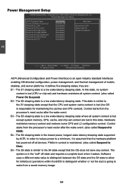
... S3 sleeping state is a low wake latency sleeping state where all system context is lost (the OS is responsible for initial boot operations within the BIOS to distinguish whether or not the boot is going to the S4 state except that the CPU and system cache context is similar to wake...
... S3 sleeping state is a low wake latency sleeping state where all system context is lost (the OS is responsible for initial boot operations within the BIOS to distinguish whether or not the boot is going to the S4 state except that the CPU and system cache context is similar to wake...


