Fluke 902 HVAC Clamp Meter Datasheet
Page 2
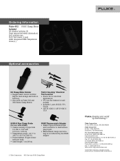
All rights reserved. Keeping your world up and running.™ Fluke Corporation PO Box 9090, Everett, WA USA 98206 Fluke Europe B.V. Ordering Information Fluke-902 HVAC Clamp Meter Included AA alkaline batteries (2) Users manual (w/safety information) Soft carrying case TL75 Test Leads (1 pair) 80BK Integrated DMM Temperature Probe (1) Optional accessories H3 Clamp Meter Holster • Rugged fabric...
All rights reserved. Keeping your world up and running.™ Fluke Corporation PO Box 9090, Everett, WA USA 98206 Fluke Europe B.V. Ordering Information Fluke-902 HVAC Clamp Meter Included AA alkaline batteries (2) Users manual (w/safety information) Soft carrying case TL75 Test Leads (1 pair) 80BK Integrated DMM Temperature Probe (1) Optional accessories H3 Clamp Meter Holster • Rugged fabric...
FE 902 Users Manual
Page 7
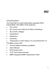
902 Introduction The Fluke 902 is a hand-held battery-operated HVAC Clamp Meter ("the Meter") that measures: • AC current • DC current (up to 200 µA for flame rod testing) • AC and DC voltages • Capacitance • Resistance • Continuity • Temperature in both Celsius (°C) and Fahrenheit (°F) The Meter comes with: • Two AA alkaline batteries (installed) • Users Manual • Soft carrying case • TL75 Test Leads (one pair) • 80BK Integrated DMM Temperature Probe 1
902 Introduction The Fluke 902 is a hand-held battery-operated HVAC Clamp Meter ("the Meter") that measures: • AC current • DC current (up to 200 µA for flame rod testing) • AC and DC voltages • Capacitance • Resistance • Continuity • Temperature in both Celsius (°C) and Fahrenheit (°F) The Meter comes with: • Two AA alkaline batteries (installed) • Users Manual • Soft carrying case • TL75 Test Leads (one pair) • 80BK Integrated DMM Temperature Probe 1

FE 902 Users Manual
Page 9
...otherwise, the Meter's safety features may be damaged. • Never measure ac current while the test leads are inserted into the input jacks. • Do not use the Meter or test leads if they look damaged. • Use extreme caution when working alone so assistance can be ...impaired. • Avoid working around bare conductors or bus bars. A "W Caution" statement identifies conditions and actions that could cause bodily harm or death. HVAC Clamp Meter Contacting Fluke Safety...
...otherwise, the Meter's safety features may be damaged. • Never measure ac current while the test leads are inserted into the input jacks. • Do not use the Meter or test leads if they look damaged. • Use extreme caution when working alone so assistance can be ...impaired. • Avoid working around bare conductors or bus bars. A "W Caution" statement identifies conditions and actions that could cause bodily harm or death. HVAC Clamp Meter Contacting Fluke Safety...
FE 902 Users Manual
Page 16
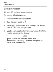
Turn the rotary switch to choose AC or DC voltage. Press A to . 3. The Meter reading appears on the display. V 2. The display reflects the chosen voltage mode. 4. Note When a measured voltage is above 30 V, Zappears on the display. Insert the test leads into the Meter. Use the test leads to take the measurement. When the voltage drops below 30 V, Zdisappears. 10 902 Users Manual Using the Meter AC and DC Voltage Measurement To measure AC or DC voltage: 1.
Turn the rotary switch to choose AC or DC voltage. Press A to . 3. The Meter reading appears on the display. V 2. The display reflects the chosen voltage mode. 4. Note When a measured voltage is above 30 V, Zappears on the display. Insert the test leads into the Meter. Use the test leads to take the measurement. When the voltage drops below 30 V, Zdisappears. 10 902 Users Manual Using the Meter AC and DC Voltage Measurement To measure AC or DC voltage: 1.

FE 902 Users Manual
Page 17
Turn the rotary switch to electrical shock and injury, de-energize the circuit before taking the measurement. 1. Take the measurement. The resistance reading appears on the display. • If the resistance is shorted, the Meter beeps and shows a reading < 30 Ω. • If the resistance is open or exceeds the Meter's range, the display reads OL. 11 P 2. HVAC Clamp Meter Using the Meter Resistance and Continuity To measure resistance or continuity: XW Warning To avoid false readings that can lead to . 3. Insert the test leads into the Meter.
Turn the rotary switch to electrical shock and injury, de-energize the circuit before taking the measurement. 1. Take the measurement. The resistance reading appears on the display. • If the resistance is shorted, the Meter beeps and shows a reading < 30 Ω. • If the resistance is open or exceeds the Meter's range, the display reads OL. 11 P 2. HVAC Clamp Meter Using the Meter Resistance and Continuity To measure resistance or continuity: XW Warning To avoid false readings that can lead to . 3. Insert the test leads into the Meter.
FE 902 Users Manual
Page 18
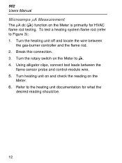
... wire. 5. Turn heating unit on and check the reading on the Meter to G. 4. Using alligator clips, connect test leads between the gas-burner controller and the flame rod. 2. Turn the rotary switch on the Meter. 6. 902 Users Manual Microamps µA Measurement The µA dc (G) function on the Meter is primarily for what the...
... wire. 5. Turn heating unit on and check the reading on the Meter to G. 4. Using alligator clips, connect test leads between the gas-burner controller and the flame rod. 2. Turn the rotary switch on the Meter. 6. 902 Users Manual Microamps µA Measurement The µA dc (G) function on the Meter is primarily for what the...
FE 902 Users Manual
Page 22
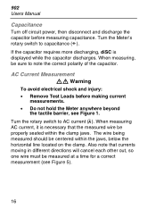
... AC current, it is displayed while the capacitor discharges. AC Current Measurement XW Warning To avoid electrical shock and injury: • Remove Test Leads before measuring capacitance. Also note that the measured wire be measured at a time for a correct measurement (see Figure 1. When measuring, ...Turn the rotary switch to note the correct polarity of the capacitor. The wire being measured should be sure to AC current (K). 902 Users Manual Capacitance Turn off circuit power, then disconnect and discharge the capacitor before making current measurements. • Do not hold the...
... AC current, it is displayed while the capacitor discharges. AC Current Measurement XW Warning To avoid electrical shock and injury: • Remove Test Leads before measuring capacitance. Also note that the measured wire be measured at a time for a correct measurement (see Figure 1. When measuring, ...Turn the rotary switch to note the correct polarity of the capacitor. The wire being measured should be sure to AC current (K). 902 Users Manual Capacitance Turn off circuit power, then disconnect and discharge the capacitor before making current measurements. • Do not hold the...

FE 902 Users Manual
Page 27
... screw. 21 Remove the batteries. 4. Reattach the battery compartment door to "OFF" and remove the test leads from the case bottom. 3. Use a Phillips screwdriver to Figure 6): 1. Replace the batteries with two new AA batteries. 5. Disconnect the test leads before replacing the batteries. To replace the batteries (refer to loosen the battery compartment door screw...
... screw. 21 Remove the batteries. 4. Reattach the battery compartment door to "OFF" and remove the test leads from the case bottom. 3. Use a Phillips screwdriver to Figure 6): 1. Replace the batteries with two new AA batteries. 5. Disconnect the test leads before replacing the batteries. To replace the batteries (refer to loosen the battery compartment door screw...


