Fluke 787 and 789 Process Meter Datasheet
Page 1
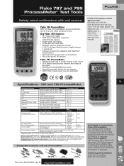
...port compatible with FlukeView® Forms Software • Improved battery power with a 4-20 mA signal applied. Ordering information Fluke-789 ProcessMeter Fluke-787 ProcessMeter For more while carrying a lot less. Fluke 787 and 789 ProcessMeter™ Test Tools Safety rated multimeters with two brightness settings ... alkaline batteries (installed), product overview and users manual (CD-ROM) in 14 languages. Key Fluke 789 features: • 24 V loop power supply • HART mode setting with loop power (adds 250 ohm resistor) • Double-sized, dual display • 20 mA drive into...
...port compatible with FlukeView® Forms Software • Improved battery power with a 4-20 mA signal applied. Ordering information Fluke-789 ProcessMeter Fluke-787 ProcessMeter For more while carrying a lot less. Fluke 787 and 789 ProcessMeter™ Test Tools Safety rated multimeters with two brightness settings ... alkaline batteries (installed), product overview and users manual (CD-ROM) in 14 languages. Key Fluke 789 features: • 24 V loop power supply • HART mode setting with loop power (adds 250 ohm resistor) • Double-sized, dual display • 20 mA drive into...

FE 789 Users Manual
Page 4
789 Users Manual Auto Ramping the mA Output 26 Power-Up Options ...27 Loop Power Supply Mode 29 Battery Life ...31 Maintenance...31 General Maintenance ...31 Calibration ...31 Replacing a Fuse...34 If the Meter does not Work 34 Replacement Parts and Accessories 35 Specifications ...39 ii
789 Users Manual Auto Ramping the mA Output 26 Power-Up Options ...27 Loop Power Supply Mode 29 Battery Life ...31 Maintenance...31 General Maintenance ...31 Calibration ...31 Replacing a Fuse...34 If the Meter does not Work 34 Replacement Parts and Accessories 35 Specifications ...39 ii

FE 789 Users Manual
Page 7
Rotary Function Switch Positions for Supplying Loop Power 30 11. Fluke 789 ProcessMeter ...5 2. Pushbuttons ...12 6. Elements of Figures Figure Title Page 1. Simulating a Transmitter ...23 9. Replacing the Batteries and Fuses 33 12. Connections for Measurements 8 4. Input/Output Jacks ...6 3. List of the Display ...15 7. Replacement Parts ...36 v Current 29 10. Rotary Function Switch Positions for mA Output 10 5. Sourcing Current...21 8. Loop Power Voltage vs.
Rotary Function Switch Positions for Supplying Loop Power 30 11. Fluke 789 ProcessMeter ...5 2. Pushbuttons ...12 6. Elements of Figures Figure Title Page 1. Simulating a Transmitter ...23 9. Replacing the Batteries and Fuses 33 12. Connections for Measurements 8 4. Input/Output Jacks ...6 3. List of the Display ...15 7. Replacement Parts ...36 v Current 29 10. Rotary Function Switch Positions for mA Output 10 5. Sourcing Current...21 8. Loop Power Voltage vs.
FE 789 Users Manual
Page 9
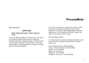
...using the meter. The Fluke 789 ProcessMeter™ (referred to test process instruments, and providing a > 24 V loop power supply. If the meter is damaged or something is a handheld, battery-operated tool for information about DMM (digital multimeter) accessories. Contact a Fluke distributor for measuring electrical ...-678-200 Japan: +81-3-3434-0181 Singapore: +65-738-5655 Anywhere in the world: +1-425-446-5500 1 Contacting Fluke To order accessories, receive operating assistance, or get the location of a digital multimeter, plus current output capability. To order replacement...
...using the meter. The Fluke 789 ProcessMeter™ (referred to test process instruments, and providing a > 24 V loop power supply. If the meter is damaged or something is a handheld, battery-operated tool for information about DMM (digital multimeter) accessories. Contact a Fluke distributor for measuring electrical ...-678-200 Japan: +81-3-3434-0181 Singapore: +65-738-5655 Anywhere in the world: +1-425-446-5500 1 Contacting Fluke To order accessories, receive operating assistance, or get the location of a digital multimeter, plus current output capability. To order replacement...
FE 789 Users Manual
Page 13
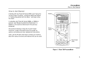
...and figures in "Getting Acquainted with Fluke 80 Series DMMs, or DMMs in general, read "Measuring Electrical Parameters" in addition to the sections referenced in the previous paragraph. Display ProcessMeter How to refresh your memory about the power-up options, and battery and ...Get Started 789 PROCESSMETER Rotary Switch 100% SpanCheck 0% MIN MAX %STEP RANGE COARSE REL HOLD FINE Hz mV V V mA A mA OFF A mA mA mA 250 HART LOOP POWER COM V Pushbuttons Input/Output Jacks Figure 1. If unfamiliar with the Meter," and begin using the meter. Fluke 789 ProcessMeter anw014f....
...and figures in "Getting Acquainted with Fluke 80 Series DMMs, or DMMs in general, read "Measuring Electrical Parameters" in addition to the sections referenced in the previous paragraph. Display ProcessMeter How to refresh your memory about the power-up options, and battery and ...Get Started 789 PROCESSMETER Rotary Switch 100% SpanCheck 0% MIN MAX %STEP RANGE COARSE REL HOLD FINE Hz mV V V mA A mA OFF A mA mA mA 250 HART LOOP POWER COM V Pushbuttons Input/Output Jacks Figure 1. If unfamiliar with the Meter," and begin using the meter. Fluke 789 ProcessMeter anw014f....

FE 789 Users Manual
Page 15
Common for loop power supply. Output for all measurements. Input for current to 24 mA. (Use in series with an external loop supply.) Common for transmitter simulation to 30 mA. Simulate Transmitter Function Output for dc current to 1000 V, Ω, continuity, and diode ... A c B mA d C V D COM Table 2. Input for up to 24 mA. Common for dc current output to 30 seconds.) Fused with an external loop supply.) 7 Input/Output Jacks Measurement Functions Source Current Function Input for current to 440 mA continuous. (1 A for voltage to 24 mA. Common for...
Common for loop power supply. Output for all measurements. Input for current to 24 mA. (Use in series with an external loop supply.) Common for transmitter simulation to 30 mA. Simulate Transmitter Function Output for dc current to 1000 V, Ω, continuity, and diode ... A c B mA d C V D COM Table 2. Input for up to 24 mA. Common for dc current output to 30 seconds.) Fused with an external loop supply.) 7 Input/Output Jacks Measurement Functions Source Current Function Input for current to 440 mA continuous. (1 A for voltage to 24 mA. Common for...

FE 789 Users Manual
Page 16
Rotary Function Switch Positions for Measurements anw002f.eps 8 789 Users Manual 4 3 2 1 5 mV 6 mA V A V mA OFF mA mA 250 HART LOOP POWER Figure 3.
Rotary Function Switch Positions for Measurements anw002f.eps 8 789 Users Manual 4 3 2 1 5 mV 6 mA V A V mA OFF mA mA 250 HART LOOP POWER Figure 3.

FE 789 Users Manual
Page 18
789 Users Manual mV mA V A 1 V mA OFF 2 mA 3 mA 250 HART LOOP POWER Figure 4. Rotary Function Switch Positions for mA Output anw008f.eps 10
789 Users Manual mV mA V A 1 V mA OFF 2 mA 3 mA 250 HART LOOP POWER Figure 4. Rotary Function Switch Positions for mA Output anw008f.eps 10

FE 789 Users Manual
Page 19
... output up or down 0.1 mA FINE X or W: Adjusts output up or down 0.001 mA E sets output to 0 % F sets output to 100 % J(Blue) cycles through : C LOOP POWER Supply > 24 V loop power, measure mA • 250 Ω series resistor for HART communication switched in 25 % steps ( pon display) • Slow repeating 0 % -100 % - 0 % ramp (m on display) Table...
... output up or down 0.1 mA FINE X or W: Adjusts output up or down 0.001 mA E sets output to 0 % F sets output to 100 % J(Blue) cycles through : C LOOP POWER Supply > 24 V loop power, measure mA • 250 Ω series resistor for HART communication switched in 25 % steps ( pon display) • Slow repeating 0 % -100 % - 0 % ramp (m on display) Table...

FE 789 Users Manual
Page 25
... % steps (15 seconds/step) p - fast ramp in 25 % steps (5 seconds/step) P 250 Ω HART Lights when 250 Ω series resistance is switched in Q Loop Power Lights when in loop supply mode 17 ProcessMeter Getting Acquainted with the numerals M or kΩ, kHz N Auto Range Range status indicators: Manual Range Auto Range - Element Meaning M mA...
... % steps (15 seconds/step) p - fast ramp in 25 % steps (5 seconds/step) P 250 Ω HART Lights when 250 Ω series resistance is switched in Q Loop Power Lights when in loop supply mode 17 ProcessMeter Getting Acquainted with the numerals M or kΩ, kHz N Auto Range Range status indicators: Manual Range Auto Range - Element Meaning M mA...

FE 789 Users Manual
Page 29
789 PROCESSMETER 100% SpanCheck 0% MIN MAX %STEP RANGE COARSE REL HOLD FINE Hz mV V V mA A mA OFF A mA mA mA 250 HART LOOP POWER COM V ProcessMeter Using the Current Output Functions 40 20 60 80 0 100 Figure 7. Sourcing Current anw010f.eps 21
789 PROCESSMETER 100% SpanCheck 0% MIN MAX %STEP RANGE COARSE REL HOLD FINE Hz mV V V mA A mA OFF A mA mA mA 250 HART LOOP POWER COM V ProcessMeter Using the Current Output Functions 40 20 60 80 0 100 Figure 7. Sourcing Current anw010f.eps 21

FE 789 Users Manual
Page 31
dc V Power Supply COM +24V 789 PROCESSMETER 100% SpanCheck 0% MIN MAX %STEP RANGE COARSE REL HOLD FINE Hz mV V V mA A mA OFF A mA mA mA 250 HART LOOP POWER COM V ProcessMeter Using the Current Output Functions 40 20 60 80 0 100 Figure 8. Simulating a Transmitter anw011f.eps 23
dc V Power Supply COM +24V 789 PROCESSMETER 100% SpanCheck 0% MIN MAX %STEP RANGE COARSE REL HOLD FINE Hz mV V V mA A mA OFF A mA mA mA 250 HART LOOP POWER COM V ProcessMeter Using the Current Output Functions 40 20 60 80 0 100 Figure 8. Simulating a Transmitter anw011f.eps 23

FE 789 Users Manual
Page 37
... resistance of 250 Ω can be switched in Loop Power Mode, the meter acts like a battery. When loop power is enabled, the meter is configured to measure mA and > 24 V dc is drawing. Loop Power Supply Mode The Loop Power Supply Mode can be used for communication with the ...instrument current loop as Figure 10 shows. Pressing J(Blue) again switches out this internal resistance. Voltage (V) ProcessMeter Loop Power Supply Mode 32 30 28 26 24 22 20...
... resistance of 250 Ω can be switched in Loop Power Mode, the meter acts like a battery. When loop power is enabled, the meter is configured to measure mA and > 24 V dc is drawing. Loop Power Supply Mode The Loop Power Supply Mode can be used for communication with the ...instrument current loop as Figure 10 shows. Pressing J(Blue) again switches out this internal resistance. Voltage (V) ProcessMeter Loop Power Supply Mode 32 30 28 26 24 22 20...

FE 789 Users Manual
Page 38
Connections for Supplying Loop Power 30 anw009f.eps Black Figure 10. 789 Users Manual 789 PROCESSMETER 100% SpanCheck 0% MIN MAX %STEP RANGE COARSE REL HOLD FINE Hz mV V V mA A mA OFF A mA mA mA 250 HART LOOP POWER COM V Red TEST DC PWR - ++ - +-
Connections for Supplying Loop Power 30 anw009f.eps Black Figure 10. 789 Users Manual 789 PROCESSMETER 100% SpanCheck 0% MIN MAX %STEP RANGE COARSE REL HOLD FINE Hz mV V V mA A mA OFF A mA mA mA 250 HART LOOP POWER COM V Red TEST DC PWR - ++ - +-

FE 789 Users Manual
Page 52
789 Users Manual Diode Test and Continuity Test Diode test indication: Displays voltage drop across device, 2.0 V full scale. Accuracy ±(2 % + 1 count). Continuity test indication: Continuous audible tone for test resistance < 100 Ω Open circuit voltage: < 2.9 V Short circuit current: 220 µA typical Overload protection: 1000 V rms Loop Power... >~4.5 V 44 Simulate Mode: Span: 0 mA or 4 mA to 20 mA, with overrange to 24 mA Accuracy: 0.05 % of span1 Loop voltage: 24 V nominal, 48 V maximum, 15 V minimum Compliance voltage: 21 V for 24 V supply Burden voltage: < 3 V General ...
789 Users Manual Diode Test and Continuity Test Diode test indication: Displays voltage drop across device, 2.0 V full scale. Accuracy ±(2 % + 1 count). Continuity test indication: Continuous audible tone for test resistance < 100 Ω Open circuit voltage: < 2.9 V Short circuit current: 220 µA typical Overload protection: 1000 V rms Loop Power... >~4.5 V 44 Simulate Mode: Span: 0 mA or 4 mA to 20 mA, with overrange to 24 mA Accuracy: 0.05 % of span1 Loop voltage: 24 V nominal, 48 V maximum, 15 V minimum Compliance voltage: 21 V for 24 V supply Burden voltage: < 3 V General ...

Calibration Manual
Page 3
Table of Contents Title Page Introduction...1 How to Contact Fluke 1 Safety Information 2 Symbols ...3 Specifications...4 Required Equipment 7 Basic Maintenance 8 Cleaning the ProcessMeter 8 Replacing the Batteries 8 Battery Life...9 Checking and Replacing the Fuses 10 Calibration Verification 10 Preparing to Perform Calibration Verification 11 Loop Power 11 Current Sourcing 13 Current Measurement 14 Checking the Diode Test...
Table of Contents Title Page Introduction...1 How to Contact Fluke 1 Safety Information 2 Symbols ...3 Specifications...4 Required Equipment 7 Basic Maintenance 8 Cleaning the ProcessMeter 8 Replacing the Batteries 8 Battery Life...9 Checking and Replacing the Fuses 10 Calibration Verification 10 Preparing to Perform Calibration Verification 11 Loop Power 11 Current Sourcing 13 Current Measurement 14 Checking the Diode Test...

Calibration Manual
Page 7
Current Measurement Test Connections 14 5. DC mV Measurement Test Connections 20 9. AC/DC Voltage Measurement Test Connections 21 10. List of Figures Figure Title Page 1. Continuity Test Connections 17 7. Resistance Measurement Test Connections 18 8. Calibration Button Access 26 12. Replacement Parts 31 v Current Sourcing Connections Using the HP 3458A 13 4. Verifying Loop Power 12 3. Diode Test Connections 16 6. Frequency Measurement Test Connections 23 11. Replacing the Batteries and Fuses 9 2.
Current Measurement Test Connections 14 5. DC mV Measurement Test Connections 20 9. AC/DC Voltage Measurement Test Connections 21 10. List of Figures Figure Title Page 1. Continuity Test Connections 17 7. Resistance Measurement Test Connections 18 8. Calibration Button Access 26 12. Replacement Parts 31 v Current Sourcing Connections Using the HP 3458A 13 4. Verifying Loop Power 12 3. Diode Test Connections 16 6. Frequency Measurement Test Connections 23 11. Replacing the Batteries and Fuses 9 2.

Calibration Manual
Page 14
789 Calibration Manual Frequency Counter Sensitivity Input Range 400 mV Minimum Sensitivity (rms Sinewave) 5 Hz to 5 kHz* AC DC (approximate trigger level 5 % of full scale) 150 ...
789 Calibration Manual Frequency Counter Sensitivity Input Range 400 mV Minimum Sensitivity (rms Sinewave) 5 Hz to 5 kHz* AC DC (approximate trigger level 5 % of full scale) 150 ...

Calibration Manual
Page 20
789 Calibration Manual Loop Power 1. Enable the dc volts autorange function of the UUT to LOOP POWER. 3. Turn the rotary knob of the HP3458A multimeter. 2. Measure the open circuit voltage of the UUT and verify it is >29.8 V and 23.8 V and 25 mA and
789 Calibration Manual Loop Power 1. Enable the dc volts autorange function of the UUT to LOOP POWER. 3. Turn the rotary knob of the HP3458A multimeter. 2. Measure the open circuit voltage of the UUT and verify it is >29.8 V and 23.8 V and 25 mA and

Quick Reference Guide
Page 1
...Hz mV V V mA A mA OFF A mA mA mA 250 HART LOOP POWER COM V CAT IV 600 V F1 Replace F1 if reading is OL mA F2 F1 Go to www.fluke.com to register your product and find more information. 789 PROCESSMETER 100% SpanCheck 0% MIN MAX %STEP RANGE COARSE REL HOLD FINE ...MIN MAX %STEP RANGE COARSE REL HOLD FINE Hz mV V V mA A mA OFF A mA mA mA 250 HART LOOP POWER COM V CAT IV 600 V 1x 2x 3x PN 4276679 August 2012 © 2012 Fluke Corporation. 789 ProcessMeter Quick Reference Guide XW Warning To prevent possible electrical shock, fire, or personal injury, read the...
...Hz mV V V mA A mA OFF A mA mA mA 250 HART LOOP POWER COM V CAT IV 600 V F1 Replace F1 if reading is OL mA F2 F1 Go to www.fluke.com to register your product and find more information. 789 PROCESSMETER 100% SpanCheck 0% MIN MAX %STEP RANGE COARSE REL HOLD FINE ...MIN MAX %STEP RANGE COARSE REL HOLD FINE Hz mV V V mA A mA OFF A mA mA mA 250 HART LOOP POWER COM V CAT IV 600 V 1x 2x 3x PN 4276679 August 2012 © 2012 Fluke Corporation. 789 ProcessMeter Quick Reference Guide XW Warning To prevent possible electrical shock, fire, or personal injury, read the...


