
Calibration Manual
Page 1
All rights reserved. All product names are subject to change without notice. Specifications are trademarks of their respective companies. 789 ProcessMeter™ Calibration Manual September 2002, Rev.1, 3/13 © 2002-2013 Fluke Corporation.
All rights reserved. All product names are subject to change without notice. Specifications are trademarks of their respective companies. 789 ProcessMeter™ Calibration Manual September 2002, Rev.1, 3/13 © 2002-2013 Fluke Corporation.

Calibration Manual
Page 4
789 Calibration Manual ii
789 Calibration Manual ii

Calibration Manual
Page 6
789 Calibration Manual iv
789 Calibration Manual iv

Calibration Manual
Page 8
789 Calibration Manual vi
789 Calibration Manual vi

Calibration Manual
Page 9
... be opened. To view, print, or download the latest manual supplement, visit http://us.fluke.com/usen/support/manuals. The Calibration Manual for handling static sensitive devices. Do not perform the calibration verification tests or calibration procedures described in this manual unless you do so. Caution The 789 ProcessMeter™ contains parts that can cause damage to the...
... be opened. To view, print, or download the latest manual supplement, visit http://us.fluke.com/usen/support/manuals. The Calibration Manual for handling static sensitive devices. Do not perform the calibration verification tests or calibration procedures described in this manual unless you do so. Caution The 789 ProcessMeter™ contains parts that can cause damage to the...
Calibration Manual
Page 10
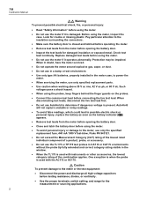
...the meter. • To avoid personal injury or damage to the meter, use only the specified replacement fuse, 440 mA 1000 V fast-blow, Fluke PN 943121. • Do not exceed the Measurement Category (CAT) rating of the lowest rated individual component of a product, probe, or accessory. ...Use caution when working above 30 V ac rms, 42 V ac pk, or 60 V dc. When disconnecting test leads, disconnect the live test lead. 789 Calibration Manual Warning To prevent possible electrical shock, fire, or personal injury: • Read "Safety Information" before using the meter. • Do...
...the meter. • To avoid personal injury or damage to the meter, use only the specified replacement fuse, 440 mA 1000 V fast-blow, Fluke PN 943121. • Do not exceed the Measurement Category (CAT) rating of the lowest rated individual component of a product, probe, or accessory. ...Use caution when working above 30 V ac rms, 42 V ac pk, or 60 V dc. When disconnecting test leads, disconnect the live test lead. 789 Calibration Manual Warning To prevent possible electrical shock, fire, or personal injury: • Read "Safety Information" before using the meter. • Do...
Calibration Manual
Page 11
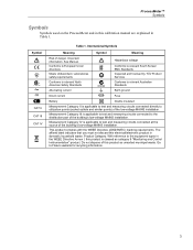
...Conforms to relevant Australian Standards Alternating current Earth ground Direct current Fuse Battery Double insulated Measurement Category II is applicable to Fluke's website for recycling information. 3 Go to test and measuring circuits connected at the source of the low-voltage MAINS installation. Important information. This ...; CAT II CAT III CAT IV Table 1. ProcessMeter™ Symbols Symbols Symbols used on the ProcessMeter and in this calibration manual are explained in domestic household waste.
...Conforms to relevant Australian Standards Alternating current Earth ground Direct current Fuse Battery Double insulated Measurement Category II is applicable to Fluke's website for recycling information. 3 Go to test and measuring circuits connected at the source of the low-voltage MAINS installation. Important information. This ...; CAT II CAT III CAT IV Table 1. ProcessMeter™ Symbols Symbols Symbols used on the ProcessMeter and in this calibration manual are explained in domestic household waste.

Calibration Manual
Page 12
... are valid from +18 °C to 100 % of the least significant digit. The standard specification interval is 1 year. All specifications assume a 5-minute warm-up period. 789 Calibration Manual Specifications All specifications apply from 5 % to +28 °C unless stated otherwise.
... are valid from +18 °C to 100 % of the least significant digit. The standard specification interval is 1 year. All specifications assume a 5-minute warm-up period. 789 Calibration Manual Specifications All specifications apply from 5 % to +28 °C unless stated otherwise.

Calibration Manual
Page 14
Nominal test current 0.2 mA at 0.6 V. Accuracy ±(2 % + 1 count). Continuity test indication: Continuous audible tone for test resistance 789 Calibration Manual Frequency Counter Sensitivity Input Range 400 mV Minimum Sensitivity (rms Sinewave) 5 Hz to 5 kHz* AC DC (approximate trigger level 5 % of full scale) 150 mV (50 ...
Nominal test current 0.2 mA at 0.6 V. Accuracy ±(2 % + 1 count). Continuity test indication: Continuous audible tone for test resistance 789 Calibration Manual Frequency Counter Sensitivity Input Range 400 mV Minimum Sensitivity (rms Sinewave) 5 Hz to 5 kHz* AC DC (approximate trigger level 5 % of full scale) 150 mV (50 ...

Calibration Manual
Page 16
... the ProcessMeter requires cleaning, wipe it down with a cloth that the slot is preferable Fluke Model 5500A Fluke 787 ProcessMeter 741,743, or 744 Process Calibrator Agilent 3458A Fluke 5440A-7002 Low Thermal Test Leads --- Lift off the battery compartment door. 4. Reinstall ...batteries. 5. Use four AA alkaline batteries. 1. With a standard blade hand screwdriver, turn the ProcessMeter OFF. 2. 789 Calibration Manual Equipment Calibration Source Digital Process Meter or Digital Process Calibrator Digital Multimeter Test Leads, low leakage, RG-58/U type 1-kΩ shunt Table 2.
... the ProcessMeter requires cleaning, wipe it down with a cloth that the slot is preferable Fluke Model 5500A Fluke 787 ProcessMeter 741,743, or 744 Process Calibrator Agilent 3458A Fluke 5440A-7002 Low Thermal Test Leads --- Lift off the battery compartment door. 4. Reinstall ...batteries. 5. Use four AA alkaline batteries. 1. With a standard blade hand screwdriver, turn the ProcessMeter OFF. 2. 789 Calibration Manual Equipment Calibration Source Digital Process Meter or Digital Process Calibrator Digital Multimeter Test Leads, low leakage, RG-58/U type 1-kΩ shunt Table 2.
Calibration Manual
Page 18
...blown. Using an ohmmeter, check the resistance between tests and before use only the specified replacement fuse, 440 mA 1000 V fast-blow, Fluke PN 943121. no adjustments are fused with the screw picture molded into the Ac input. 3. Merely make the required connections, source the ...that fuse F2 is parallel with separate 440 mA fuses. Using an ohmmeter, check the resistance between the ProcessMeter test leads. 789 Calibration Manual Checking and Replacing the Fuses Warning To avoid personal injury or damage to . 5. Both current input jacks are necessary....
...blown. Using an ohmmeter, check the resistance between tests and before use only the specified replacement fuse, 440 mA 1000 V fast-blow, Fluke PN 943121. no adjustments are fused with the screw picture molded into the Ac input. 3. Merely make the required connections, source the ...that fuse F2 is parallel with separate 440 mA fuses. Using an ohmmeter, check the resistance between the ProcessMeter test leads. 789 Calibration Manual Checking and Replacing the Fuses Warning To avoid personal injury or damage to . 5. Both current input jacks are necessary....

Calibration Manual
Page 20
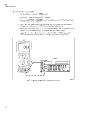
Enable the dc volts autorange function of the UUT to LOOP POWER. 3. Turn the rotary knob of the HP3458A multimeter. 2. Measure the open circuit voltage of the UUT and verify it is >29.8 V and 23.8 V and 25 mA and 789 Calibration Manual Loop Power 1.
Enable the dc volts autorange function of the UUT to LOOP POWER. 3. Turn the rotary knob of the HP3458A multimeter. 2. Measure the open circuit voltage of the UUT and verify it is >29.8 V and 23.8 V and 25 mA and 789 Calibration Manual Loop Power 1.

Calibration Manual
Page 22
789 Calibration Manual Current Measurement 1. Apply the values from the calibrator shown in Table 7 and compare the readings on the UUT to the acceptable readings shown. 5. W 2. Current Measurement Test Connections adm003F.EPS 14 Connect the calibrator to the COM and mA terminals on the UUT to ...the acceptable readings shown. 7. Apply the values from the calibrator shown in Figure 4. 4. Put the calibrator in the position. 3. Apply the values from the calibrator shown in Table 5 and compare the readings on the UUT as shown in Table 5...
789 Calibration Manual Current Measurement 1. Apply the values from the calibrator shown in Table 7 and compare the readings on the UUT to the acceptable readings shown. 5. W 2. Current Measurement Test Connections adm003F.EPS 14 Connect the calibrator to the COM and mA terminals on the UUT to ...the acceptable readings shown. 7. Apply the values from the calibrator shown in Figure 4. 4. Put the calibrator in the position. 3. Apply the values from the calibrator shown in Table 5 and compare the readings on the UUT as shown in Table 5...
Calibration Manual
Page 26
789 Calibration Manual Resistance Measurement Test 1. Connect the OUTPUT and SENSE leads of the calibrator resistance values in Figure 7. 4. Compare the readings on the UUT to the UUT as shown by the solid and dotted lines in Table 8 (400 kΩ range and above). Apply the calibrator resistance ... lines in the 789 400 Ω to the UUT. Resistance Measurement Test Connections adm004F.EPS 18 Change the connections to 40 kΩ range. Put the calibrator in the V position. 3. Using the Fluke 5440A-7002 low thermal leads, connect the calibrator to the acceptable ...
789 Calibration Manual Resistance Measurement Test 1. Connect the OUTPUT and SENSE leads of the calibrator resistance values in Figure 7. 4. Compare the readings on the UUT to the UUT as shown by the solid and dotted lines in Table 8 (400 kΩ range and above). Apply the calibrator resistance ... lines in the 789 400 Ω to the UUT. Resistance Measurement Test Connections adm004F.EPS 18 Change the connections to 40 kΩ range. Put the calibrator in the V position. 3. Using the Fluke 5440A-7002 low thermal leads, connect the calibrator to the acceptable ...

Calibration Manual
Page 28
... in Standby (STBY) mode. 2. Put the calibrator in the U position. 3. Apply the values from the calibrator shown in Table 9 and compare the readings on the UUT as shown in Figure 8. 4. DC mV Measurement Test Connections adm005F.EPS 789 Range No Range Switching No Range Switching Table ...5500A Figure 8. Connect the calibrator to the COM and terminals on the UUT to the acceptable readings shown. DC mV Test Calibrator DC Voltage Minimum Reading 100 mV 300 mV 99.8 mV 299.6 mV Maximum Reading 100.2 mV 300.4 mV 20 789 Calibration Manual DC Millivolts Measurement Test 1....
... in Standby (STBY) mode. 2. Put the calibrator in the U position. 3. Apply the values from the calibrator shown in Table 9 and compare the readings on the UUT as shown in Figure 8. 4. DC mV Measurement Test Connections adm005F.EPS 789 Range No Range Switching No Range Switching Table ...5500A Figure 8. Connect the calibrator to the COM and terminals on the UUT to the acceptable readings shown. DC mV Test Calibrator DC Voltage Minimum Reading 100 mV 300 mV 99.8 mV 299.6 mV Maximum Reading 100.2 mV 300.4 mV 20 789 Calibration Manual DC Millivolts Measurement Test 1....

Calibration Manual
Page 30
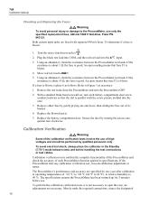
...To prevent possible electrical shock, fire, or personal injury: • Some of the calibration verification tests involve the use of high voltages and should be performed by qualified personnel only. • Always place the calibrator in Figure 9. 4. 789 Calibration Manual 789 Range 4 V dc 4 V dc 40 V dc 40 V dc 400 V ...dc 400 V dc 1000 V dc 1000 V dc Table 10. Apply the values from the calibrator shown in Table 11 and compare the readings on...
...To prevent possible electrical shock, fire, or personal injury: • Some of the calibration verification tests involve the use of high voltages and should be performed by qualified personnel only. • Always place the calibrator in Figure 9. 4. 789 Calibration Manual 789 Range 4 V dc 4 V dc 40 V dc 40 V dc 400 V ...dc 400 V dc 1000 V dc 1000 V dc Table 10. Apply the values from the calibrator shown in Table 11 and compare the readings on...

Calibration Manual
Page 32
... • Do not use the ProcessMeter if it appears to its specifications. contact Fluke to have the ProcessMeter serviced. • To avoid electrical shock, always place the calibrator in the Standby (STBY) mode between tests and before using a closed and latched... into the ProcessMeter might be performed by qualified personnel only. 24 Calibrate the ProcessMeter once a year to ensure that the battery compartment door on the ProcessMeter is closed -case procedure. 789 Calibration Manual Calibration Adjustment The ProcessMeter is detected, do not continue; Replace damaged test...
... • Do not use the ProcessMeter if it appears to its specifications. contact Fluke to have the ProcessMeter serviced. • To avoid electrical shock, always place the calibrator in the Standby (STBY) mode between tests and before using a closed and latched... into the ProcessMeter might be performed by qualified personnel only. 24 Calibrate the ProcessMeter once a year to ensure that the battery compartment door on the ProcessMeter is closed -case procedure. 789 Calibration Manual Calibration Adjustment The ProcessMeter is detected, do not continue; Replace damaged test...

Calibration Manual
Page 34
... after the sourced value appears. Press and hold the Calibration Button for approximately 2 seconds. The unit will remain in calibration mode. 5. Push h. 4. Connect the ProcessMeter to store the calibration value. 26 789 Calibration Manual Calibration Button Figure 11. Turn the UUT's switch to S. 3. Note Pressing the Calibration Button puts the ProcessMeter into and out of the 5500A...
... after the sourced value appears. Press and hold the Calibration Button for approximately 2 seconds. The unit will remain in calibration mode. 5. Push h. 4. Connect the ProcessMeter to store the calibration value. 26 789 Calibration Manual Calibration Button Figure 11. Turn the UUT's switch to S. 3. Note Pressing the Calibration Button puts the ProcessMeter into and out of the 5500A...

Calibration Manual
Page 36
789 Calibration Manual DC Millivolts Adjustment 1. Turn the UUT's switch to V. 3. The ProcessMeter will remain in calibration mode until the unit is turned off or the calibration button is displayed, press to the volt/ohm output of the 5500A calibrator. 2. Do not alter the sourced value while the display reads Busy. 6. Press and hold the Calibration...; 40 kΩ • 400 kΩ • 4 MΩ • 40 MΩ 5. CAL appears in calibration mode. 4. Ohms Adjustment 1. Press after the sourced value appears. Turn the UUT's switch to U. 3. Do not...
789 Calibration Manual DC Millivolts Adjustment 1. Turn the UUT's switch to V. 3. The ProcessMeter will remain in calibration mode until the unit is turned off or the calibration button is displayed, press to the volt/ohm output of the 5500A calibrator. 2. Do not alter the sourced value while the display reads Busy. 6. Press and hold the Calibration...; 40 kΩ • 400 kΩ • 4 MΩ • 40 MΩ 5. CAL appears in calibration mode. 4. Ohms Adjustment 1. Press after the sourced value appears. Turn the UUT's switch to U. 3. Do not...

Calibration Manual
Page 38
... a 20.000 on the 3458. 3. Make sure the test leads are in the A and COM jacks. 3. Press J (BLUE) to store calibration constants. Press after the reading stabilizes. 5. Milliamps Output Adjustment 1. 789 Calibration Manual Amps DC Adjustment 1. The unit will output approximately 4 mA. Apply 0 A dc. Fuse will blow after 30 seconds. 6. Press after...
... a 20.000 on the 3458. 3. Make sure the test leads are in the A and COM jacks. 3. Press J (BLUE) to store calibration constants. Press after the reading stabilizes. 5. Milliamps Output Adjustment 1. 789 Calibration Manual Amps DC Adjustment 1. The unit will output approximately 4 mA. Apply 0 A dc. Fuse will blow after 30 seconds. 6. Press after...


