Fluke 725 Process Calibrator Datasheet
Page 1
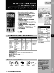
...:1994 Class B Size (HxWxD): 200 mm x 96 mm x 47 mm (7.9 in x 3.8 in x 1.9 in 14 languages. Squarewave, 1 CPM to10 kHz; Ordering information Fluke-724 Temperature Calibrator (also see page 26) Fluke-725 Multifunction Process Calibrator Simultaneous function capability 24.000 mA DC 24.000 mA DC with simultaneous mA measurement • Store frequently-used for later...
...:1994 Class B Size (HxWxD): 200 mm x 96 mm x 47 mm (7.9 in x 3.8 in x 1.9 in 14 languages. Squarewave, 1 CPM to10 kHz; Ordering information Fluke-724 Temperature Calibrator (also see page 26) Fluke-725 Multifunction Process Calibrator Simultaneous function capability 24.000 mA DC 24.000 mA DC with simultaneous mA measurement • Store frequently-used for later...

FE 725ex Users Manual
Page 1
January 2005 Rev.1, 8/05 © 2005 Fluke Corporation, All rights reserved. Printed in USA All product names are trademarks of their respective companies. ® 725Ex Multifunction Process Calibrator Users Manual
January 2005 Rev.1, 8/05 © 2005 Fluke Corporation, All rights reserved. Printed in USA All product names are trademarks of their respective companies. ® 725Ex Multifunction Process Calibrator Users Manual

FE 725ex Users Manual
Page 11
... allows the user to the functions in USA: 1-888-99-FLUKE (1-888-993-5853) Or, visit Fluke's Web site at www.fluke.com. The Fluke 725Ex Multifunction Process Calibrator (hereafter referred to measure volts, current, and pressure only. The upper display allows the user to as "the Calibrator") is a handheld, battery-operated instrument that measures and sources electrical...
... allows the user to the functions in USA: 1-888-99-FLUKE (1-888-993-5853) Or, visit Fluke's Web site at www.fluke.com. The Fluke 725Ex Multifunction Process Calibrator (hereafter referred to measure volts, current, and pressure only. The upper display allows the user to as "the Calibrator") is a handheld, battery-operated instrument that measures and sources electrical...

FE 725ex Users Manual
Page 20
...;C • Manufactured by Martel Electronics, Inc., 1F Commons Drive Londonderry, NH, USA Getting Acquainted with the Calibrator Input and Output Terminals Figure 2 shows the Calibrator input and output terminals. 725Ex Users Manual Certification Information • P ( II 1 G EEx ia IIB 171 °C 0344 KEMA 04ATEX1303X... B,C,D RECALL Hz ˚C ˚F 100% 25% 25% 0% 2 8 3 7 654 aly05f.eps Figure 2. Table 3 explains their use. 10 1 725Ex MULTIFUNCTION PROCESS CALIBRATOR V mA LOOP ZERO MEAS SOURCE STORE SETUP V mA TC RTD 2004.1573266 LR110460 Zone 0 AEx ia IIB 171 C I.S.
...;C • Manufactured by Martel Electronics, Inc., 1F Commons Drive Londonderry, NH, USA Getting Acquainted with the Calibrator Input and Output Terminals Figure 2 shows the Calibrator input and output terminals. 725Ex Users Manual Certification Information • P ( II 1 G EEx ia IIB 171 °C 0344 KEMA 04ATEX1303X... B,C,D RECALL Hz ˚C ˚F 100% 25% 25% 0% 2 8 3 7 654 aly05f.eps Figure 2. Table 3 explains their use. 10 1 725Ex MULTIFUNCTION PROCESS CALIBRATOR V mA LOOP ZERO MEAS SOURCE STORE SETUP V mA TC RTD 2004.1573266 LR110460 Zone 0 AEx ia IIB 171 C I.S.

FE 725ex Users Manual
Page 22
... SCHÉMA DE CONNEXION: FLUKE 725Ex CCD 0% 30V MAX ALL TERMINALS SOURCE / MEASURE mA+ 3W V TC Hz RTD MEASURE V mA LOOP mA- 4W COM COM Figure 3. Keys 12 6 7 8 9 10 11 aly41f.eps Class I .S. 725Ex Users Manual Keys Figure 3 shows the Calibrator keys and Table 4 explains their use. 725Ex MULTIFUNCTION PROCESS CALIBRATOR 2 V mA LOOP ZERO MEAS V mA...
... SCHÉMA DE CONNEXION: FLUKE 725Ex CCD 0% 30V MAX ALL TERMINALS SOURCE / MEASURE mA+ 3W V TC Hz RTD MEASURE V mA LOOP mA- 4W COM COM Figure 3. Keys 12 6 7 8 9 10 11 aly41f.eps Class I .S. 725Ex Users Manual Keys Figure 3 shows the Calibrator keys and Table 4 explains their use. 725Ex MULTIFUNCTION PROCESS CALIBRATOR 2 V mA LOOP ZERO MEAS V mA...

FE 725ex Users Manual
Page 28
Press and hold W to save the contrast level. 18 725Ex MULTIFUNCTION PROCESS CALIBRATOR 1 V mA LOOP ZERO 2 MEAS SOURCE V mA TC RTD Hz ˚C ˚F STORE SETUP RECALL 100% 25% 25% 4 0% 3 Figure 6. Press S to lighten contrast. 4. Press and hold Xto darken contrast. 3. Adjusting the Contrast sh06f.eps 725Ex Users Manual Contrast Adjustment To adjust the contrast, proceed as shown in Figure 6. 2. Press C and O until Contst Adjust is displayed as follows: 1.
Press and hold W to save the contrast level. 18 725Ex MULTIFUNCTION PROCESS CALIBRATOR 1 V mA LOOP ZERO 2 MEAS SOURCE V mA TC RTD Hz ˚C ˚F STORE SETUP RECALL 100% 25% 25% 4 0% 3 Figure 6. Press S to lighten contrast. 4. Press and hold Xto darken contrast. 3. Adjusting the Contrast sh06f.eps 725Ex Users Manual Contrast Adjustment To adjust the contrast, proceed as shown in Figure 6. 2. Press C and O until Contst Adjust is displayed as follows: 1.
FE 725ex Users Manual
Page 29
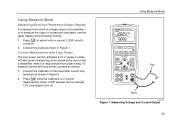
...of a pressure instrument, use the upper display and proceed as shown in Figure 8. 2. Measuring Voltage and Current Output 19 Connect the Calibrator to the transmitter current loop terminals as follows: 1. LOOP appears and an internal 12-V loop supply turns on . 2. Current Measurement ...LOOP should not be on . To measure current with the current measuring circuit, allowing the user to select volts or current. Using Measure Mode 725Ex MULTIFUNCTION PROCESS CALIBRATOR V mA LOOP ZERO MEAS SOURCE STORE SETUP V mA TC RTD 2004.1573266 LR110460 Zone 0 AEx ia IIB 171 C I Div 1, Groups...
...of a pressure instrument, use the upper display and proceed as shown in Figure 8. 2. Measuring Voltage and Current Output 19 Connect the Calibrator to the transmitter current loop terminals as follows: 1. LOOP appears and an internal 12-V loop supply turns on . 2. Current Measurement ...LOOP should not be on . To measure current with the current measuring circuit, allowing the user to select volts or current. Using Measure Mode 725Ex MULTIFUNCTION PROCESS CALIBRATOR V mA LOOP ZERO MEAS SOURCE STORE SETUP V mA TC RTD 2004.1573266 LR110460 Zone 0 AEx ia IIB 171 C I Div 1, Groups...
FE 725ex Users Manual
Page 30
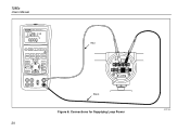
Connections for Supplying Loop Power 20 aly18f.eps 725Ex Users Manual 725Ex MULTIFUNCTION PROCESS CALIBRATOR V mA LOOP ZERO MEAS SOURCE STORE SETUP V mA TC RTD 2004.1573266 LR110460 Zone 0 AEx ia IIB 171 C I Div 1, Groups B,C,D RECALL Hz ˚C ˚F 100% 25% 25% 0% Red TEST DC PWR - ++ - +- Black Figure 8. Class I .S.
Connections for Supplying Loop Power 20 aly18f.eps 725Ex Users Manual 725Ex MULTIFUNCTION PROCESS CALIBRATOR V mA LOOP ZERO MEAS SOURCE STORE SETUP V mA TC RTD 2004.1573266 LR110460 Zone 0 AEx ia IIB 171 C I Div 1, Groups B,C,D RECALL Hz ˚C ˚F 100% 25% 25% 0% Red TEST DC PWR - ++ - +- Black Figure 8. Class I .S.

FE 725ex Users Manual
Page 31
..., press for frequency or resistance. Class I .S. Using Measure Mode 725Ex MULTIFUNCTION PROCESS CALIBRATOR V mA LOOP ZERO MEAS SOURCE STORE SETUP V mA TC RTD 2004.1573266 LR110460 Zone 0 AEx ia IIB 171 C I Div 1, Groups B,C,D RECALL Hz ˚C ˚F 100% 25% 25% 0% aly43f.eps Figure 9. Connect the Calibrator as follows: 1. Press V for dc voltage or current...
..., press for frequency or resistance. Class I .S. Using Measure Mode 725Ex MULTIFUNCTION PROCESS CALIBRATOR V mA LOOP ZERO MEAS SOURCE STORE SETUP V mA TC RTD 2004.1573266 LR110460 Zone 0 AEx ia IIB 171 C I Div 1, Groups B,C,D RECALL Hz ˚C ˚F 100% 25% 25% 0% aly43f.eps Figure 9. Connect the Calibrator as follows: 1. Press V for dc voltage or current...

FE 725ex Users Manual
Page 40
Connections for Measuring Pressure aly37f.eps 30 Class I .S. 725Ex Users Manual 725Ex MULTIFUNCTION PROCESS CALIBRATOR V mA LOOP ZERO MEAS SOURCE STORE SETUP V mA TC RTD 2004.1573266 LR110460 Zone 0 AEx ia IIB 171 C I Div 1, Groups B,C,D RECALL Hz ˚C ˚F 100% 25% 25% 0% Gage Module Isolation Valve Differential Module L H Tank Figure 13.
Connections for Measuring Pressure aly37f.eps 30 Class I .S. 725Ex Users Manual 725Ex MULTIFUNCTION PROCESS CALIBRATOR V mA LOOP ZERO MEAS SOURCE STORE SETUP V mA TC RTD 2004.1573266 LR110460 Zone 0 AEx ia IIB 171 C I Div 1, Groups B,C,D RECALL Hz ˚C ˚F 100% 25% 25% 0% Gage Module Isolation Valve Differential Module L H Tank Figure 13.
FE 725ex Users Manual
Page 42
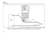
Figure 14. Connections for Simulating a 4 to Fluke 725Ex CCD Control Drawing when using in a non-Ex hazardous Area aly17f.eps 32 Refer to 20- mA Transmitter in an Ex hazardous area. 725Ex Users Manual 725Ex MULTIFUNCTION PROCESS CALIBRATOR + Loop Power Supply Red V mA LOOP ZERO MEAS SOURCE STORE SETUP V mA TC RTD 2004.1573266 LR110460 Zone 0 AEx ia IIB 171 C I Div 1, Groups B,C,D RECALL Hz ˚C ˚F 100% 25% 25% 0% Black Readout or Controller - Class I .S.
Figure 14. Connections for Simulating a 4 to Fluke 725Ex CCD Control Drawing when using in a non-Ex hazardous Area aly17f.eps 32 Refer to 20- mA Transmitter in an Ex hazardous area. 725Ex Users Manual 725Ex MULTIFUNCTION PROCESS CALIBRATOR + Loop Power Supply Red V mA LOOP ZERO MEAS SOURCE STORE SETUP V mA TC RTD 2004.1573266 LR110460 Zone 0 AEx ia IIB 171 C I Div 1, Groups B,C,D RECALL Hz ˚C ˚F 100% 25% 25% 0% Black Readout or Controller - Class I .S.
FE 725ex Users Manual
Page 45
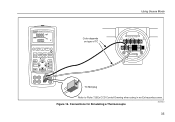
Connections for Simulating a Thermocouple aly20f.eps 35 Class I .S. Figure 16. TC TC Miniplug Refer to Fluke 725Ex CCD Control Drawing when using in an Ex hazardous area. Using Source Mode 725Ex MULTIFUNCTION PROCESS CALIBRATOR V mA LOOP ZERO MEAS SOURCE STORE SETUP V mA TC RTD 2004.1573266 LR110460 Zone 0 AEx ia IIB 171 C I Div 1, Groups B,C,D RECALL Hz ˚C ˚F 100% 25% 25% 0% Color depends on type of TC TEST DC PWR - ++ +-
Connections for Simulating a Thermocouple aly20f.eps 35 Class I .S. Figure 16. TC TC Miniplug Refer to Fluke 725Ex CCD Control Drawing when using in an Ex hazardous area. Using Source Mode 725Ex MULTIFUNCTION PROCESS CALIBRATOR V mA LOOP ZERO MEAS SOURCE STORE SETUP V mA TC RTD 2004.1573266 LR110460 Zone 0 AEx ia IIB 171 C I Div 1, Groups B,C,D RECALL Hz ˚C ˚F 100% 25% 25% 0% Color depends on type of TC TEST DC PWR - ++ +-

FE 725ex Users Manual
Page 48
...Modules vary in zeroing procedures depending on the pressure modules accept standard ¼ NPT pipe fittings. Press U (lower display). The Calibrator automatically senses which pressure module is attached and sets its range accordingly. 3. Zero the pressure module as shown in the module's...;C, cmH O@20 °C, inH O@4 °C, inH O@20 °C, 2 2 2 inH O@60 °F, mbar, bar, kg/cm2, or kPa. 2 725Ex MULTIFUNCTION PROCESS CALIBRATOR V mA LOOP ZERO MEAS SOURCE STORE SETUP V mA TC RTD 2004.1573266 LR110460 Zone 0 AEx ia IIB 171 C I Div 1, Groups B,C,D RECALL Hz ˚...
...Modules vary in zeroing procedures depending on the pressure modules accept standard ¼ NPT pipe fittings. Press U (lower display). The Calibrator automatically senses which pressure module is attached and sets its range accordingly. 3. Zero the pressure module as shown in the module's...;C, cmH O@20 °C, inH O@4 °C, inH O@20 °C, 2 2 2 inH O@60 °F, mbar, bar, kg/cm2, or kPa. 2 725Ex MULTIFUNCTION PROCESS CALIBRATOR V mA LOOP ZERO MEAS SOURCE STORE SETUP V mA TC RTD 2004.1573266 LR110460 Zone 0 AEx ia IIB 171 C I Div 1, Groups B,C,D RECALL Hz ˚...

FE 725ex Users Manual
Page 52
Calibrating a Thermocouple Transmitter aly44f.eps 42 Class I .S. Figure 19. 725Ex Users Manual 725Ex MULTIFUNCTION PROCESS CALIBRATOR V mA LOOP ZERO MEAS SOURCE STORE SETUP V mA TC RTD 2004.1573266 LR110460 Zone 0 AEx ia IIB 171 C I Div 1, Groups B,C,D RECALL Hz ˚C ˚F 100% 25% 25% 0% Red TEST DC PWR - ++ - +- Black Refer to Fluke 725Ex CCD Control Drawing when using in an Ex hazardous area.
Calibrating a Thermocouple Transmitter aly44f.eps 42 Class I .S. Figure 19. 725Ex Users Manual 725Ex MULTIFUNCTION PROCESS CALIBRATOR V mA LOOP ZERO MEAS SOURCE STORE SETUP V mA TC RTD 2004.1573266 LR110460 Zone 0 AEx ia IIB 171 C I Div 1, Groups B,C,D RECALL Hz ˚C ˚F 100% 25% 25% 0% Red TEST DC PWR - ++ - +- Black Refer to Fluke 725Ex CCD Control Drawing when using in an Ex hazardous area.
FE 725ex Users Manual
Page 54
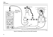
Class I Div 1, Groups B,C,D RECALL Hz ˚C ˚F 100% 25% 25% 0% Pressure Module Red Black Refer to -Current (P/I .S. Calibrating a Pressure-to Fluke 725Ex CCD Control Drawing when using in an Ex hazardous area. Figure 20. 725Ex Users Manual 725Ex MULTIFUNCTION PROCESS CALIBRATOR Measure mA Source Pressure 12 V Loop Power Enabled Hand Pump SIGNAL + - TEST 44 V mA LOOP ZERO MEAS SOURCE STORE SETUP V mA TC RTD 2004.1573266 LR110460 Zone 0 AEx ia IIB 171 C I ) Transmitter aly34f.eps
Class I Div 1, Groups B,C,D RECALL Hz ˚C ˚F 100% 25% 25% 0% Pressure Module Red Black Refer to -Current (P/I .S. Calibrating a Pressure-to Fluke 725Ex CCD Control Drawing when using in an Ex hazardous area. Figure 20. 725Ex Users Manual 725Ex MULTIFUNCTION PROCESS CALIBRATOR Measure mA Source Pressure 12 V Loop Power Enabled Hand Pump SIGNAL + - TEST 44 V mA LOOP ZERO MEAS SOURCE STORE SETUP V mA TC RTD 2004.1573266 LR110460 Zone 0 AEx ia IIB 171 C I ) Transmitter aly34f.eps

FE 725ex Users Manual
Page 56
Calibrating a Current-to Fluke 725Ex CCD Control Drawing when using in an Ex hazardous area. 725Ex Users Manual 725Ex MULTIFUNCTION PROCESS CALIBRATOR Measure Pressure Source mA SIGNAL + - TEST 46 V mA LOOP ZERO MEAS SOURCE STORE SETUP V mA TC RTD 2004.1573266 LR110460 Zone 0 AEx ia IIB 171 C I /P) Transmitter aly28f.eps Figure 21. Class I Div 1, Groups B,C,D RECALL Hz ˚C ˚F 100% 25% 25% 0% Pressure Module Red Black Refer to -Pressure (I .S.
Calibrating a Current-to Fluke 725Ex CCD Control Drawing when using in an Ex hazardous area. 725Ex Users Manual 725Ex MULTIFUNCTION PROCESS CALIBRATOR Measure Pressure Source mA SIGNAL + - TEST 46 V mA LOOP ZERO MEAS SOURCE STORE SETUP V mA TC RTD 2004.1573266 LR110460 Zone 0 AEx ia IIB 171 C I /P) Transmitter aly28f.eps Figure 21. Class I Div 1, Groups B,C,D RECALL Hz ˚C ˚F 100% 25% 25% 0% Pressure Module Red Black Refer to -Pressure (I .S.

FE 725ex Users Manual
Page 58
... necessary, press for frequency or resistance (lower display). Proceed as shown in an Ex hazardous area. Calibrating a Chart Recorder Connect the test leads to Fluke 725Ex CCD Control Drawing when using in Figure 22. 2. Class I .S. 725Ex Users Manual Testing an Output Device Use the source functions to 1 V dc Input V mA LOOP ... to the instrument under test as follows: 1. aly25f.eps Figure 22. Press V for current or dc voltage, or F for SOURCE mode. 48 725Ex MULTIFUNCTION PROCESS CALIBRATOR Red 0 to test and calibrate actuators, recording, and indicating devices.
... necessary, press for frequency or resistance (lower display). Proceed as shown in an Ex hazardous area. Calibrating a Chart Recorder Connect the test leads to Fluke 725Ex CCD Control Drawing when using in Figure 22. 2. Class I .S. 725Ex Users Manual Testing an Output Device Use the source functions to 1 V dc Input V mA LOOP ... to the instrument under test as follows: 1. aly25f.eps Figure 22. Press V for current or dc voltage, or F for SOURCE mode. 48 725Ex MULTIFUNCTION PROCESS CALIBRATOR Red 0 to test and calibrate actuators, recording, and indicating devices.

FE 725ex Users Manual
Page 65
... V 0.02 % + 2 90 mV 0.01 mV 0.02 % + 2 Temperature coefficient -10 °C to 18 °C, +28 °C to 55 °C: ±0.005 % of range per °C Multifunction Process Calibrator Specifications DC Voltage Source Range Resolution Accuracy, (% of Reading + Counts) 100 mV 0.01 mV 0.02 % + 2 10 V 0.001 V 0.02 % + 2 Temperature coefficient -10 °C to 18 °...
... V 0.02 % + 2 90 mV 0.01 mV 0.02 % + 2 Temperature coefficient -10 °C to 18 °C, +28 °C to 55 °C: ±0.005 % of range per °C Multifunction Process Calibrator Specifications DC Voltage Source Range Resolution Accuracy, (% of Reading + Counts) 100 mV 0.01 mV 0.02 % + 2 10 V 0.001 V 0.02 % + 2 Temperature coefficient -10 °C to 18 °...

FE 725ex Users Manual
Page 67
... 500 °C 500 to 1750 °C Measure and Source Accuracies 1.0 °C 0.7 °C 1.2 °C 0.8 °C 1.2 °C 0.8 °C 0.9 °C 0.7 °C 2.5 °C 1.8 °C 1.4 °C 2.5 °C 1.8 °C 1.5 °C Multifunction Process Calibrator Specifications Type Range B 600 to 800 °C 800 to 1000 °C 1000 to 1800 °C L -200 to 0 °C 0 to 900 °C U -200 to 0 °C 0 to...
... 500 °C 500 to 1750 °C Measure and Source Accuracies 1.0 °C 0.7 °C 1.2 °C 0.8 °C 1.2 °C 0.8 °C 0.9 °C 0.7 °C 2.5 °C 1.8 °C 1.4 °C 2.5 °C 1.8 °C 1.5 °C Multifunction Process Calibrator Specifications Type Range B 600 to 800 °C 800 to 1000 °C 1000 to 1800 °C L -200 to 0 °C 0 to 900 °C U -200 to 0 °C 0 to...

FE 725ex Users Manual
Page 69
... module General Specifications Operating temperature Storage temperature Operating altitude Relative Humidity (% RH operating without condensation) Vibration Product Compliance Markings EMC Power requirements Size Weight Multifunction Process Calibrator Specifications Units psi, inH2O@4 °C, inH2O@20 °C, inH2O@60 °F, kPa, cmH2O@4 °C, cmH2O@20 °C, bar, mbar, kg/cm2, mmHg, inHg -10 °...
... module General Specifications Operating temperature Storage temperature Operating altitude Relative Humidity (% RH operating without condensation) Vibration Product Compliance Markings EMC Power requirements Size Weight Multifunction Process Calibrator Specifications Units psi, inH2O@4 °C, inH2O@20 °C, inH2O@60 °F, kPa, cmH2O@4 °C, cmH2O@20 °C, bar, mbar, kg/cm2, mmHg, inHg -10 °...

