
FE 725ex Users Manual
Page 1
Printed in USA All product names are trademarks of their respective companies. ® 725Ex Multifunction Process Calibrator Users Manual January 2005 Rev.1, 8/05 © 2005 Fluke Corporation, All rights reserved.
Printed in USA All product names are trademarks of their respective companies. ® 725Ex Multifunction Process Calibrator Users Manual January 2005 Rev.1, 8/05 © 2005 Fluke Corporation, All rights reserved.

FE 725ex Users Manual
Page 11
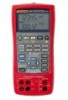
...; Stores and recalls setups. • Manual stepping and automatic stepping and ramping. For a summary of the nearest Fluke distributor or Service Center, call: USA: 1-888-44-FLUKE (1-888-443-5853) Canada: 1-800-36-FLUKE (1-800-363-5853) Europe: +31 402-675-200 Japan: +81-3-3434-0181 Singapore: +65-738-5655 Anywhere...upper display allows the user to as "the Calibrator") is a handheld, battery-operated instrument that measures and sources electrical and physical parameters. The Fluke 725Ex Multifunction Process Calibrator (hereafter referred to measure volts, current, and pressure only.
...; Stores and recalls setups. • Manual stepping and automatic stepping and ramping. For a summary of the nearest Fluke distributor or Service Center, call: USA: 1-888-44-FLUKE (1-888-443-5853) Canada: 1-800-36-FLUKE (1-800-363-5853) Europe: +31 402-675-200 Japan: +81-3-3434-0181 Singapore: +65-738-5655 Anywhere...upper display allows the user to as "the Calibrator") is a handheld, battery-operated instrument that measures and sources electrical and physical parameters. The Fluke 725Ex Multifunction Process Calibrator (hereafter referred to measure volts, current, and pressure only.

FE 725ex Users Manual
Page 12
...725Ex Users Manual Function dc V dc mA Frequency Resistance Thermocouple RTD (ResistanceTemperature Detector) Pressure Other functions Table 1. H2O to 3200 Ω Types E, J, K, T, B, R, S, L, U, N, mV, XK, BP Ni120 Pt100 Ω (385) Pt100 Ω (3926) Pt100 Ω (3916) Pt200 Ω (385) Pt500 Ω (385) Pt1000 Ω (385) Fluke... 700PEx series modules ranging from 10 in . H2O to 3,000 psi Fluke 700PEx series modules ranging from 10 in . Summary of Source and Measure Functions Measure 0 V dc...
...725Ex Users Manual Function dc V dc mA Frequency Resistance Thermocouple RTD (ResistanceTemperature Detector) Pressure Other functions Table 1. H2O to 3200 Ω Types E, J, K, T, B, R, S, L, U, N, mV, XK, BP Ni120 Pt100 Ω (385) Pt100 Ω (3926) Pt100 Ω (3916) Pt200 Ω (385) Pt500 Ω (385) Pt1000 Ω (385) Fluke... 700PEx series modules ranging from 10 in . H2O to 3,000 psi Fluke 700PEx series modules ranging from 10 in . Summary of Source and Measure Functions Measure 0 V dc...
FE 725ex Users Manual
Page 13
... 9. • TL75 test leads (one set) • AC72 alligator clips (one set) • Stackable alligator clip test leads (one set) • Fluke 725Ex CD-ROM (contains Fluke 725Ex Users Manual) • Fluke 725Ex CCD • Fluke 725Ex Safety Information • 4 AA Batteries (installed) • Hex Key, 5/64 in this manual are explained in Figure 1 are included with the...
... 9. • TL75 test leads (one set) • AC72 alligator clips (one set) • Stackable alligator clip test leads (one set) • Fluke 725Ex CD-ROM (contains Fluke 725Ex Users Manual) • Fluke 725Ex CCD • Fluke 725Ex Safety Information • 4 AA Batteries (installed) • Hex Key, 5/64 in this manual are explained in Figure 1 are included with the...
FE 725ex Users Manual
Page 14
... open circuit voltage parameter (Voc) and a maximum short circuit current parameter (Isc). The Model 725Ex calibrator will be a source of the cable in the intrinsically safe circuit. Again, Fluke 725Ex CCD identifies the maximum capacitance (Ca) and maximum inductance (La) that capacitance and inductance has...the other equipment must not exceed the maximum allowed capacitance (Ca). As an example, Fluke 725Ex CCD explains that Voc of either on the intrinsic safety barrier ratings or on Fluke 725Ex CCD. In this case, the maximum allowed inductance (La) will be determined using ...
... open circuit voltage parameter (Voc) and a maximum short circuit current parameter (Isc). The Model 725Ex calibrator will be a source of the cable in the intrinsically safe circuit. Again, Fluke 725Ex CCD identifies the maximum capacitance (Ca) and maximum inductance (La) that capacitance and inductance has...the other equipment must not exceed the maximum allowed capacitance (Ca). As an example, Fluke 725Ex CCD explains that Voc of either on the intrinsic safety barrier ratings or on Fluke 725Ex CCD. In this case, the maximum allowed inductance (La) will be determined using ...
FE 725ex Users Manual
Page 15
... test leads. • When using the Calibrator. See "Ex Hazardous Areas". • Replace the battery as soon as described in this User Manual and the Fluke 725Ex CCD (Concept Control Drawing) or the protection provided by the Calibrator may result in permanent damage to the unit so it appears damaged. • Check...
... test leads. • When using the Calibrator. See "Ex Hazardous Areas". • Replace the battery as soon as described in this User Manual and the Fluke 725Ex CCD (Concept Control Drawing) or the protection provided by the Calibrator may result in permanent damage to the unit so it appears damaged. • Check...
FE 725ex Users Manual
Page 19
... entity parameters. The safety features and integrity of the unit is known to be restricted to any circuits that exceed the entity parameters defined on Fluke 725Ex CCD Control Drawing. See "Ex Hazardous Areas". • Do not carry additional batteries within the Ex-hazardous area. See "Ex Hazardous Areas". • Use only...
... entity parameters. The safety features and integrity of the unit is known to be restricted to any circuits that exceed the entity parameters defined on Fluke 725Ex CCD Control Drawing. See "Ex Hazardous Areas". • Do not carry additional batteries within the Ex-hazardous area. See "Ex Hazardous Areas". • Use only...

FE 725ex Users Manual
Page 22
... ALL TERMINALS SOURCE / MEASURE mA+ 3W V TC Hz RTD MEASURE V mA LOOP mA- 4W COM COM 3 4 5 20 19 18 17 16 15 14 1133 12 725Ex MULTIFUNCTION PROCESS CALIBRATOR V mA LOOP ZERO MEAS SOURCE STORE SETUP V mA TC RTD 2004.1573266 LR110460 Zone 0 AEx ia IIB 171... IIC T4 ZELM 02 ATEX 0120 Hz ˚C ˚F 100% 25% 25% REFER TO CONTROL DRAWING: ANSCHLUSSSCHEMA BEACHTEN: SUIVRE LE SCHÉMA DE CONNEXION: FLUKE 725Ex CCD 0% 30V MAX ALL TERMINALS SOURCE / MEASURE mA+ 3W V TC Hz RTD MEASURE V mA LOOP mA- 4W COM COM Figure 3.
... ALL TERMINALS SOURCE / MEASURE mA+ 3W V TC Hz RTD MEASURE V mA LOOP mA- 4W COM COM 3 4 5 20 19 18 17 16 15 14 1133 12 725Ex MULTIFUNCTION PROCESS CALIBRATOR V mA LOOP ZERO MEAS SOURCE STORE SETUP V mA TC RTD 2004.1573266 LR110460 Zone 0 AEx ia IIB 171... IIC T4 ZELM 02 ATEX 0120 Hz ˚C ˚F 100% 25% 25% REFER TO CONTROL DRAWING: ANSCHLUSSSCHEMA BEACHTEN: SUIVRE LE SCHÉMA DE CONNEXION: FLUKE 725Ex CCD 0% 30V MAX ALL TERMINALS SOURCE / MEASURE mA+ 3W V TC Hz RTD MEASURE V mA LOOP mA- 4W COM COM Figure 3.

FE 725ex Users Manual
Page 38
...pressure module fittings, or between the pressure module fitting and connecting fittings or adapters. • To avoid damaging the pressure module from Fluke. See "Accessories" near the back of the module. To measure pressure, attach the appropriate pressure module for the process pressure to... be tested Proceed as follows to measure pressure: W Warning Use only Fluke 700PEx series pressure modules. 725Ex Users Manual Measuring Pressure Many ranges and types of pressure in a pressurized system, shut off the valve and slowly bleed...
...pressure module fittings, or between the pressure module fitting and connecting fittings or adapters. • To avoid damaging the pressure module from Fluke. See "Accessories" near the back of the module. To measure pressure, attach the appropriate pressure module for the process pressure to... be tested Proceed as follows to measure pressure: W Warning Use only Fluke 700PEx series pressure modules. 725Ex Users Manual Measuring Pressure Many ranges and types of pressure in a pressurized system, shut off the valve and slowly bleed...
FE 725ex Users Manual
Page 42
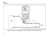
Refer to 20- mA Transmitter in an Ex hazardous area. Class I .S. Figure 14. Connections for Simulating a 4 to Fluke 725Ex CCD Control Drawing when using in a non-Ex hazardous Area aly17f.eps 32 725Ex Users Manual 725Ex MULTIFUNCTION PROCESS CALIBRATOR + Loop Power Supply Red V mA LOOP ZERO MEAS SOURCE STORE SETUP V mA TC RTD 2004.1573266 LR110460 Zone 0 AEx ia IIB 171 C I Div 1, Groups B,C,D RECALL Hz ˚C ˚F 100% 25% 25% 0% Black Readout or Controller -
Refer to 20- mA Transmitter in an Ex hazardous area. Class I .S. Figure 14. Connections for Simulating a 4 to Fluke 725Ex CCD Control Drawing when using in a non-Ex hazardous Area aly17f.eps 32 725Ex Users Manual 725Ex MULTIFUNCTION PROCESS CALIBRATOR + Loop Power Supply Red V mA LOOP ZERO MEAS SOURCE STORE SETUP V mA TC RTD 2004.1573266 LR110460 Zone 0 AEx ia IIB 171 C I Div 1, Groups B,C,D RECALL Hz ˚C ˚F 100% 25% 25% 0% Black Readout or Controller -

FE 725ex Users Manual
Page 43
Red Black Using Source Mode 30V 24mA MAX ALL TERMINALS +mmAS+AOURCE / MEASURE V 3W TC Hz RTD MEASURE V mA LOOP mA- 4W COM COM Common V Hz + Device Under Test - Electrical Sourcing Connections aly16f.eps 33 Red 30V 24mA MAX ALL TERMINALS SOURCE / MEASURE mA+ 3W V TC Hz RTD MEASURE V mA LOOP mA- 4W COM COM Black Common Refer to Fluke 725Ex CCD Control Drawing when using in an Ex hazardous area. mA + - Figure 15.
Red Black Using Source Mode 30V 24mA MAX ALL TERMINALS +mmAS+AOURCE / MEASURE V 3W TC Hz RTD MEASURE V mA LOOP mA- 4W COM COM Common V Hz + Device Under Test - Electrical Sourcing Connections aly16f.eps 33 Red 30V 24mA MAX ALL TERMINALS SOURCE / MEASURE mA+ 3W V TC Hz RTD MEASURE V mA LOOP mA- 4W COM COM Black Common Refer to Fluke 725Ex CCD Control Drawing when using in an Ex hazardous area. mA + - Figure 15.
FE 725ex Users Manual
Page 45
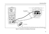
Connections for Simulating a Thermocouple aly20f.eps 35 TC TC Miniplug Refer to Fluke 725Ex CCD Control Drawing when using in an Ex hazardous area. Using Source Mode 725Ex MULTIFUNCTION PROCESS CALIBRATOR V mA LOOP ZERO MEAS SOURCE STORE SETUP V mA TC RTD 2004.1573266 LR110460 Zone 0 AEx ia IIB 171 C I Div 1, Groups B,C,D RECALL Hz ˚C ˚F 100% 25% 25% 0% Color depends on type of TC TEST DC PWR - ++ +- Class I .S. Figure 16.
Connections for Simulating a Thermocouple aly20f.eps 35 TC TC Miniplug Refer to Fluke 725Ex CCD Control Drawing when using in an Ex hazardous area. Using Source Mode 725Ex MULTIFUNCTION PROCESS CALIBRATOR V mA LOOP ZERO MEAS SOURCE STORE SETUP V mA TC RTD 2004.1573266 LR110460 Zone 0 AEx ia IIB 171 C I Div 1, Groups B,C,D RECALL Hz ˚C ˚F 100% 25% 25% 0% Color depends on type of TC TEST DC PWR - ++ +- Class I .S. Figure 16.

FE 725ex Users Manual
Page 46
Zone 0 Class I .S. Connections for Simulating 3-Wire RTD aly40f.eps 36 725Ex Users Manual 725Ex PMRUOLCTIEFSUSNCCTAIOLINBRATOR V mA LOOP ZERO MEAS SOURCE SSETTOURPE RECALL V mA TC RTD I ADEivLx21iR0a,01GII41rBo.01u14p75s167B0C3,2C,6D6 Hz ˚C ˚F 100% 25% 25% 0% Black Black Sensor Terminals 1 4 3 2 Red Refer to Fluke 725Ex CCD Control Drawing when using in an Ex hazardous area. Figure 17.
Zone 0 Class I .S. Connections for Simulating 3-Wire RTD aly40f.eps 36 725Ex Users Manual 725Ex PMRUOLCTIEFSUSNCCTAIOLINBRATOR V mA LOOP ZERO MEAS SOURCE SSETTOURPE RECALL V mA TC RTD I ADEivLx21iR0a,01GII41rBo.01u14p75s167B0C3,2C,6D6 Hz ˚C ˚F 100% 25% 25% 0% Black Black Sensor Terminals 1 4 3 2 Red Refer to Fluke 725Ex CCD Control Drawing when using in an Ex hazardous area. Figure 17.

FE 725ex Users Manual
Page 52
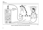
Class I .S. Figure 19. 725Ex Users Manual 725Ex MULTIFUNCTION PROCESS CALIBRATOR V mA LOOP ZERO MEAS SOURCE STORE SETUP V mA TC RTD 2004.1573266 LR110460 Zone 0 AEx ia IIB 171 C I Div 1, Groups B,C,D RECALL Hz ˚C ˚F 100% 25% 25% 0% Red TEST DC PWR - ++ - +- Calibrating a Thermocouple Transmitter aly44f.eps 42 Black Refer to Fluke 725Ex CCD Control Drawing when using in an Ex hazardous area.
Class I .S. Figure 19. 725Ex Users Manual 725Ex MULTIFUNCTION PROCESS CALIBRATOR V mA LOOP ZERO MEAS SOURCE STORE SETUP V mA TC RTD 2004.1573266 LR110460 Zone 0 AEx ia IIB 171 C I Div 1, Groups B,C,D RECALL Hz ˚C ˚F 100% 25% 25% 0% Red TEST DC PWR - ++ - +- Calibrating a Thermocouple Transmitter aly44f.eps 42 Black Refer to Fluke 725Ex CCD Control Drawing when using in an Ex hazardous area.
FE 725ex Users Manual
Page 54
Calibrating a Pressure-to Fluke 725Ex CCD Control Drawing when using in an Ex hazardous area. Class I Div 1, Groups B,C,D RECALL Hz ˚C ˚F 100% 25% 25% 0% Pressure Module Red Black Refer to -Current (P/I .S. TEST 44 V mA LOOP ZERO MEAS SOURCE STORE SETUP V mA TC RTD 2004.1573266 LR110460 Zone 0 AEx ia IIB 171 C I ) Transmitter aly34f.eps Figure 20. 725Ex Users Manual 725Ex MULTIFUNCTION PROCESS CALIBRATOR Measure mA Source Pressure 12 V Loop Power Enabled Hand Pump SIGNAL + -
Calibrating a Pressure-to Fluke 725Ex CCD Control Drawing when using in an Ex hazardous area. Class I Div 1, Groups B,C,D RECALL Hz ˚C ˚F 100% 25% 25% 0% Pressure Module Red Black Refer to -Current (P/I .S. TEST 44 V mA LOOP ZERO MEAS SOURCE STORE SETUP V mA TC RTD 2004.1573266 LR110460 Zone 0 AEx ia IIB 171 C I ) Transmitter aly34f.eps Figure 20. 725Ex Users Manual 725Ex MULTIFUNCTION PROCESS CALIBRATOR Measure mA Source Pressure 12 V Loop Power Enabled Hand Pump SIGNAL + -

FE 725ex Users Manual
Page 56
Figure 21. Class I Div 1, Groups B,C,D RECALL Hz ˚C ˚F 100% 25% 25% 0% Pressure Module Red Black Refer to -Pressure (I .S. 725Ex Users Manual 725Ex MULTIFUNCTION PROCESS CALIBRATOR Measure Pressure Source mA SIGNAL + - TEST 46 V mA LOOP ZERO MEAS SOURCE STORE SETUP V mA TC RTD 2004.1573266 LR110460 Zone 0 AEx ia IIB 171 C I /P) Transmitter aly28f.eps Calibrating a Current-to Fluke 725Ex CCD Control Drawing when using in an Ex hazardous area.
Figure 21. Class I Div 1, Groups B,C,D RECALL Hz ˚C ˚F 100% 25% 25% 0% Pressure Module Red Black Refer to -Pressure (I .S. 725Ex Users Manual 725Ex MULTIFUNCTION PROCESS CALIBRATOR Measure Pressure Source mA SIGNAL + - TEST 46 V mA LOOP ZERO MEAS SOURCE STORE SETUP V mA TC RTD 2004.1573266 LR110460 Zone 0 AEx ia IIB 171 C I /P) Transmitter aly28f.eps Calibrating a Current-to Fluke 725Ex CCD Control Drawing when using in an Ex hazardous area.

FE 725ex Users Manual
Page 58
... frequency or resistance (lower display). Calibrating a Chart Recorder Press V for current or dc voltage, or F for SOURCE mode. 48 725Ex MULTIFUNCTION PROCESS CALIBRATOR Red 0 to the instrument under test as follows: 1. 725Ex Users Manual Testing an Output Device Use the source functions to Fluke 725Ex CCD Control Drawing when using in Figure 22. 2. Class I .S. M 3.
... frequency or resistance (lower display). Calibrating a Chart Recorder Press V for current or dc voltage, or F for SOURCE mode. 48 725Ex MULTIFUNCTION PROCESS CALIBRATOR Red 0 to the instrument under test as follows: 1. 725Ex Users Manual Testing an Output Device Use the source functions to Fluke 725Ex CCD Control Drawing when using in Figure 22. 2. Class I .S. M 3.
FE 725ex Users Manual
Page 61
... charge. The Fluke 725Ex Calibrator covered by the warranty will be promptly repaired or replaced (at Fluke's option) and returned to you at the beginning of the manual. Replacement Parts Table 9 lists the part number of the title page for warranty terms. ... in transit. Pressure modules do not need to accompany the Calibrator unless the module is available. Send the equipment postage paid and insured, to "Contacting Fluke" at no responsibility for repair. To locate an authorized service center or order replacement parts, refer to the nearest Service Center. See the back of...
... charge. The Fluke 725Ex Calibrator covered by the warranty will be promptly repaired or replaced (at Fluke's option) and returned to you at the beginning of the manual. Replacement Parts Table 9 lists the part number of the title page for warranty terms. ... in transit. Pressure modules do not need to accompany the Calibrator unless the module is available. Send the equipment postage paid and insured, to "Contacting Fluke" at no responsibility for repair. To locate an authorized service center or order replacement parts, refer to the nearest Service Center. See the back of...
FE 725ex Users Manual
Page 62
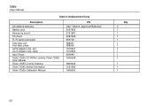
Approved Batteries" 2097832 2151981 2097826 855742 688051 688066 1670641 1670652 690948 2406548 6800032 2151996 2406553 Qty. 4 1 1 1 1 1 1 1 1 1 1 1 1 1 52 725Ex Users Manual Table 9. Replacement Parts Description AA alkaline batteries Battery door Accessory mount Tilt stand TL75 series test leads Test lead, red Test lead, black AC72 alligator clip, red AC72 alligator clip, black Input Decal Fluke 725Ex CD ROM, contains Fluke 725Ex User Manual Fluke 725Ex Control Drawing Fluke 725Ex Safety Information Fluke 725Ex Calibration Manual PN See "Table 8.
Approved Batteries" 2097832 2151981 2097826 855742 688051 688066 1670641 1670652 690948 2406548 6800032 2151996 2406553 Qty. 4 1 1 1 1 1 1 1 1 1 1 1 1 1 52 725Ex Users Manual Table 9. Replacement Parts Description AA alkaline batteries Battery door Accessory mount Tilt stand TL75 series test leads Test lead, red Test lead, black AC72 alligator clip, red AC72 alligator clip, black Input Decal Fluke 725Ex CD ROM, contains Fluke 725Ex User Manual Fluke 725Ex Control Drawing Fluke 725Ex Safety Information Fluke 725Ex Calibration Manual PN See "Table 8.

FE 725ex Users Manual
Page 70
725Ex Users Manual Entity Parameters For Entity Parameters, Refer to Fluke 725Ex CCD, Control Drawing for use in Ex hazardous areas. 60
725Ex Users Manual Entity Parameters For Entity Parameters, Refer to Fluke 725Ex CCD, Control Drawing for use in Ex hazardous areas. 60


