Fluke 725 Process Calibrator Datasheet
Page 1
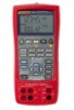
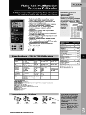
...and transmitters • Source/simulate volts, mA, thermocouples, RTDs, frequency, ohms, and pressure to calibrate transmitters • Measure/source1 pressure using any of 29 Fluke 700Pxx Pressure Modules • Source mA with simultaneous pressure measurement to conduct valve and I/P tests &#...On 724, mA is often based on 725 only M or S M or S M used for process calibrators Application Note (Literature code 1261947) Selection of range + 1 LSD 0.10 Ω to www.fluke.com/725 Included accessories TL75 Test Leads, AC72 Test Clips, one pair of stackable test leads, product overview...
...and transmitters • Source/simulate volts, mA, thermocouples, RTDs, frequency, ohms, and pressure to calibrate transmitters • Measure/source1 pressure using any of 29 Fluke 700Pxx Pressure Modules • Source mA with simultaneous pressure measurement to conduct valve and I/P tests &#...On 724, mA is often based on 725 only M or S M or S M used for process calibrators Application Note (Literature code 1261947) Selection of range + 1 LSD 0.10 Ω to www.fluke.com/725 Included accessories TL75 Test Leads, AC72 Test Clips, one pair of stackable test leads, product overview...

FE 725ex Users Manual
Page 1
Printed in USA All product names are trademarks of their respective companies. ® 725Ex Multifunction Process Calibrator Users Manual January 2005 Rev.1, 8/05 © 2005 Fluke Corporation, All rights reserved.
Printed in USA All product names are trademarks of their respective companies. ® 725Ex Multifunction Process Calibrator Users Manual January 2005 Rev.1, 8/05 © 2005 Fluke Corporation, All rights reserved.
FE 725ex Users Manual
Page 3
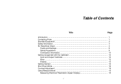
Table of Contents Title Page Introduction ...1 Contacting Fluke ...1 Standard Equipment...3 Safety Information ...3 Ex Hazardous Areas ...3 Faults and Damage 8 Safety Regulations ...9 Certification Information 10 Getting Acquainted with the Calibrator 10 Input and Output Terminals 10 Keys ...12 Display...15 Getting Started ...16 Shut Down Mode...16 Contrast Adjustment...18 Using Measure Mode ...19 Measuring Electrical Parameters (Upper Display 19 i
Table of Contents Title Page Introduction ...1 Contacting Fluke ...1 Standard Equipment...3 Safety Information ...3 Ex Hazardous Areas ...3 Faults and Damage 8 Safety Regulations ...9 Certification Information 10 Getting Acquainted with the Calibrator 10 Input and Output Terminals 10 Keys ...12 Display...15 Getting Started ...16 Shut Down Mode...16 Contrast Adjustment...18 Using Measure Mode ...19 Measuring Electrical Parameters (Upper Display 19 i
FE 725ex Users Manual
Page 4
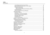
to 20 mA 31 Simulating a 4- 725Ex Users Manual Current Measurement with Loop Power 19 Measuring Electrical Parameters (Lower Display 21 Measuring Temperature 22 Using Thermocouples 22 Using Resistance-Temperature Detectors (... 39 Stepping and Ramping the Output 39 Manually Stepping the mA Output 39 Auto Ramping the Output 40 Storing and Recalling Setups 40 Calibrating a Transmitter 41 Calibrating a Pressure Transmitter 43 Calibrating an I/P Device 45 Switch Test ...47 Testing an Output Device 48 Replacing the Batteries 49 Approved Batteries ...50 Maintenance ...50 Cleaning ...
to 20 mA 31 Simulating a 4- 725Ex Users Manual Current Measurement with Loop Power 19 Measuring Electrical Parameters (Lower Display 21 Measuring Temperature 22 Using Thermocouples 22 Using Resistance-Temperature Detectors (... 39 Stepping and Ramping the Output 39 Manually Stepping the mA Output 39 Auto Ramping the Output 40 Storing and Recalling Setups 40 Calibrating a Transmitter 41 Calibrating a Pressure Transmitter 43 Calibrating an I/P Device 45 Switch Test ...47 Testing an Output Device 48 Replacing the Batteries 49 Approved Batteries ...50 Maintenance ...50 Cleaning ...
FE 725ex Users Manual
Page 5
Contents (continued) Service Center Calibration or Repair 50 Replacement Parts ...51 Accessories ...53 Specifications ...55 DC Voltage Measurement 55 DC Voltage Source...55 Millivolt Measurement and Source 55 DC mA Measurement and Source 56 Ohms Measurement 56 Ohms Source...56 Frequency Measurement 56 Frequency Source ...57 Temperature, Thermocouples 57 Loop Power Supply 57 RTD Excitation (simulation 58 Temperature, RTD Ranges, and Accuracies 58 Pressure Measurement 59 General Specifications 59 iii
Contents (continued) Service Center Calibration or Repair 50 Replacement Parts ...51 Accessories ...53 Specifications ...55 DC Voltage Measurement 55 DC Voltage Source...55 Millivolt Measurement and Source 55 DC mA Measurement and Source 56 Ohms Measurement 56 Ohms Source...56 Frequency Measurement 56 Frequency Source ...57 Temperature, Thermocouples 57 Loop Power Supply 57 RTD Excitation (simulation 58 Temperature, RTD Ranges, and Accuracies 58 Pressure Measurement 59 General Specifications 59 iii
FE 725ex Users Manual
Page 10
Calibrating a Pressure-to -Pressure (I ) Transmitter 44 21. Calibrating a Current-to -Current (P/I /P) Transmitter 46 22. Replacing the Batteries ...49 viii 725Ex Users Manual 18. Calibrating a Thermocouple Transmitter 42 20. Calibrating a Chart Recorder 48 23. Connections for Sourcing Pressure 38 19.
Calibrating a Pressure-to -Pressure (I ) Transmitter 44 21. Calibrating a Current-to -Current (P/I /P) Transmitter 46 22. Replacing the Batteries ...49 viii 725Ex Users Manual 18. Calibrating a Thermocouple Transmitter 42 20. Calibrating a Chart Recorder 48 23. Connections for Sourcing Pressure 38 19.

FE 725ex Users Manual
Page 11
...resistance temperature detectors, thermocouples, frequency, and ohms. • Calibrates a transmitter using the Calibrator. To register this product, visit register.fluke.com 1 The upper display allows the user to as "the Calibrator") is a handheld, battery-operated instrument that measures and sources... 1-888-99-FLUKE (1-888-993-5853) Or, visit Fluke's Web site at www.fluke.com. Contacting Fluke To order accessories, receive operating assistance, or get the location of source and measurement functions, see Table 1. The Fluke 725Ex Multifunction Process Calibrator (hereafter referred ...
...resistance temperature detectors, thermocouples, frequency, and ohms. • Calibrates a transmitter using the Calibrator. To register this product, visit register.fluke.com 1 The upper display allows the user to as "the Calibrator") is a handheld, battery-operated instrument that measures and sources... 1-888-99-FLUKE (1-888-993-5853) Or, visit Fluke's Web site at www.fluke.com. Contacting Fluke To order accessories, receive operating assistance, or get the location of source and measurement functions, see Table 1. The Fluke 725Ex Multifunction Process Calibrator (hereafter referred ...
FE 725ex Users Manual
Page 13
... clip test leads (one set) • Fluke 725Ex CD-ROM (contains Fluke 725Ex Users Manual) • Fluke 725Ex CCD • Fluke 725Ex Safety Information • 4 AA Batteries (installed) • Hex Key, 5/64 in., short arm Safety Information A Warning statement identifies conditions and actions that provide power to equipment that may damage the Calibrator or the equipment under test. These...
... clip test leads (one set) • Fluke 725Ex CD-ROM (contains Fluke 725Ex Users Manual) • Fluke 725Ex CCD • Fluke 725Ex Safety Information • 4 AA Batteries (installed) • Hex Key, 5/64 in., short arm Safety Information A Warning statement identifies conditions and actions that provide power to equipment that may damage the Calibrator or the equipment under test. These...
FE 725ex Users Manual
Page 14
... ratings or on the other equipment must not exceed the maximum allowed capacitance (Ca). This value will itself be reduced. When connecting the 725Ex calibrator into a powered circuit, i.e. Each set of voltage and current. The Model 725Ex calibrator will have to on Fluke 725Ex CCD. 725Ex Users Manual such as CSA C22.2 No. 157 or UL 913.
... ratings or on the other equipment must not exceed the maximum allowed capacitance (Ca). This value will itself be reduced. When connecting the 725Ex calibrator into a powered circuit, i.e. Each set of voltage and current. The Model 725Ex calibrator will have to on Fluke 725Ex CCD. 725Ex Users Manual such as CSA C22.2 No. 157 or UL 913.
FE 725ex Users Manual
Page 15
... battery door. See "Ex Hazardous Areas". • Replace the battery as soon as described in this User Manual and the Fluke 725Ex CCD (Concept Control Drawing) or the protection provided by the Calibrator may result in permanent damage to the unit so it appears damaged. • Check the test leads for the measuring...
... battery door. See "Ex Hazardous Areas". • Replace the battery as soon as described in this User Manual and the Fluke 725Ex CCD (Concept Control Drawing) or the protection provided by the Calibrator may result in permanent damage to the unit so it appears damaged. • Check the test leads for the measuring...

FE 725ex Users Manual
Page 16
... and depressurized before connecting it or disconnecting it from the pressure module. • Use four properly installed AA batteries to power the Calibrator. • Use only the batteries listed in Table 8. • Disconnect test leads from the circuit under test before testing resistance ...Approval. • Do not allow water inside the case. • Before each use only specified replacement parts. 725Ex Users Manual • When servicing the Calibrator, use , verify the Calibrator's operation by measuring a known voltage. • Never touch the probe to a voltage source when the test ...
... and depressurized before connecting it or disconnecting it from the pressure module. • Use four properly installed AA batteries to power the Calibrator. • Use only the batteries listed in Table 8. • Disconnect test leads from the circuit under test before testing resistance ...Approval. • Do not allow water inside the case. • Before each use only specified replacement parts. 725Ex Users Manual • When servicing the Calibrator, use , verify the Calibrator's operation by measuring a known voltage. • Never touch the probe to a voltage source when the test ...
FE 725ex Users Manual
Page 18
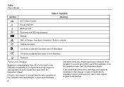
... Faults and Damage Applying a voltage greater than 30 V to the input of the Calibrator invalidates its Ex Approval and may impair its safe operation in an Ex-hazardous area. Refer to relevant European Union directives. See "Ex Hazardous Areas". 725Ex Users Manual Symbol F + J ( M W T ) Table 2. Important information. P Conforms to manual. Direct Current Power...
... Faults and Damage Applying a voltage greater than 30 V to the input of the Calibrator invalidates its Ex Approval and may impair its safe operation in an Ex-hazardous area. Refer to relevant European Union directives. See "Ex Hazardous Areas". 725Ex Users Manual Symbol F + J ( M W T ) Table 2. Important information. P Conforms to manual. Direct Current Power...
FE 725ex Users Manual
Page 19
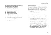
...type tested batteries. The safety features and integrity of the unit may exceed 30 V. • Only use of the Calibrator meets the requirements of the regulations providing that the user observes and applies the requirements as stated in circuits with compatible entity... • Functioning errors or obvious measurement inaccuracies occur which prevent further measurement by the Calibrator • Opening the case Ex Hazardous Areas Safety Regulations The use the Calibrator in the regulations and that exceed the entity parameters defined on Fluke 725Ex CCD Control Drawing.
...type tested batteries. The safety features and integrity of the unit may exceed 30 V. • Only use of the Calibrator meets the requirements of the regulations providing that the user observes and applies the requirements as stated in circuits with compatible entity... • Functioning errors or obvious measurement inaccuracies occur which prevent further measurement by the Calibrator • Opening the case Ex Hazardous Areas Safety Regulations The use the Calibrator in the regulations and that exceed the entity parameters defined on Fluke 725Ex CCD Control Drawing.

FE 725ex Users Manual
Page 20
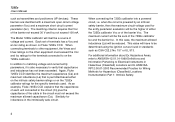
...;C 0344 KEMA 04ATEX1303X • ) Class I Div. 1 Groups B,C, and D LR110460 Class I .S. Table 3 explains their use. 10 1 725Ex MULTIFUNCTION PROCESS CALIBRATOR V mA LOOP ZERO MEAS SOURCE STORE SETUP V mA TC RTD 2004.1573266 LR110460 Zone 0 AEx ia IIB 171 C I Zone 0 Aex/Ex...176;C... +55 °C • Manufactured by Martel Electronics, Inc., 1F Commons Drive Londonderry, NH, USA Getting Acquainted with the Calibrator Input and Output Terminals Figure 2 shows the Calibrator input and output terminals. Class I Div 1, Groups B,C,D RECALL Hz ˚C ˚F 100% 25% 25% 0% 2 8 ...
...;C 0344 KEMA 04ATEX1303X • ) Class I Div. 1 Groups B,C, and D LR110460 Class I .S. Table 3 explains their use. 10 1 725Ex MULTIFUNCTION PROCESS CALIBRATOR V mA LOOP ZERO MEAS SOURCE STORE SETUP V mA TC RTD 2004.1573266 LR110460 Zone 0 AEx ia IIB 171 C I Zone 0 Aex/Ex...176;C... +55 °C • Manufactured by Martel Electronics, Inc., 1F Commons Drive Londonderry, NH, USA Getting Acquainted with the Calibrator Input and Output Terminals Figure 2 shows the Calibrator input and output terminals. Class I Div 1, Groups B,C,D RECALL Hz ˚C ˚F 100% 25% 25% 0% 2 8 ...
FE 725ex Users Manual
Page 21
...and RTDs. Terminal for sourcing and measuring current, and performing 3W and 4W RTD measurements. 11 This terminal accepts a miniature polarized thermocouple plug with the Calibrator No A B, C D E, F G, H Table 3. Terminals for measuring or simulating thermocouples. Input/Output Terminals and Connectors Name Description Pressure module connector...TC input/output SOURCE/ MEASURE V, RTD, Hz, Ω terminals SOURCE/ MEASURE mA terminals, 3W, 4W Connects the Calibrator to center. Getting Acquainted with flat, inline blades spaced 7.9 mm (0.312 in) center to a pressure module.
...and RTDs. Terminal for sourcing and measuring current, and performing 3W and 4W RTD measurements. 11 This terminal accepts a miniature polarized thermocouple plug with the Calibrator No A B, C D E, F G, H Table 3. Terminals for measuring or simulating thermocouples. Input/Output Terminals and Connectors Name Description Pressure module connector...TC input/output SOURCE/ MEASURE V, RTD, Hz, Ω terminals SOURCE/ MEASURE mA terminals, 3W, 4W Connects the Calibrator to center. Getting Acquainted with flat, inline blades spaced 7.9 mm (0.312 in) center to a pressure module.

FE 725ex Users Manual
Page 22
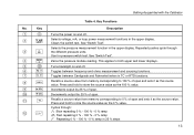
... SCHÉMA DE CONNEXION: FLUKE 725Ex CCD 0% 30V MAX ALL TERMINALS SOURCE / MEASURE mA+ 3W V TC Hz RTD MEASURE V mA LOOP mA- 4W COM COM Figure 3. Class I .S. Keys 12 6 7 8 9 10 11 aly41f.eps 725Ex Users Manual Keys Figure 3 shows the Calibrator keys and Table 4 explains their use. 725Ex MULTIFUNCTION PROCESS CALIBRATOR 2 V mA LOOP ZERO MEAS...
... SCHÉMA DE CONNEXION: FLUKE 725Ex CCD 0% 30V MAX ALL TERMINALS SOURCE / MEASURE mA+ 3W V TC Hz RTD MEASURE V mA LOOP mA- 4W COM COM Figure 3. Class I .S. Keys 12 6 7 8 9 10 11 aly41f.eps 725Ex Users Manual Keys Figure 3 shows the Calibrator keys and Table 4 explains their use. 725Ex MULTIFUNCTION PROCESS CALIBRATOR 2 V mA LOOP ZERO MEAS...
FE 725ex Users Manual
Page 23
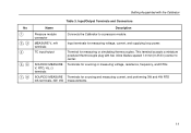
... and sourcing functions. Cycles through C A the different pressure units. Key Description A O Turns the power on and off . Clears the switch test. Getting Acquainted with the Calibrator Table 4. See "Switch Test". K J Recalls a source value from memory corresponding to 100 % of span. Use for pressure switch test. E C Turns backlight on and off . I Decrements...
... and sourcing functions. Cycles through C A the different pressure units. Key Description A O Turns the power on and off . Clears the switch test. Getting Acquainted with the Calibrator Table 4. See "Switch Test". K J Recalls a source value from memory corresponding to 100 % of span. Use for pressure switch test. E C Turns backlight on and off . I Decrements...
FE 725ex Users Manual
Page 24
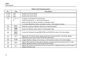
... through MEASURE and SOURCE modes in lower display. Cycles through the thermocouple types. Retrieves a previous calibrator setup from a memory location. Saves the Calibrator setup. Selects the TC (thermocouple) measurement and sourcing function in the lower display. In Contrast Adjustment... source level. Repeated pushes cycle through the 2-, 3-, and 4-wire selections. Repeated pushes cycle through the memory locations of calibrator setups. Selects the pressure measurement and sourcing function. Moves through the RTD types. up-darkens contrast, down-lightens contrast....
... through MEASURE and SOURCE modes in lower display. Cycles through the thermocouple types. Retrieves a previous calibrator setup from a memory location. Saves the Calibrator setup. Selects the TC (thermocouple) measurement and sourcing function in the lower display. In Contrast Adjustment... source level. Repeated pushes cycle through the 2-, 3-, and 4-wire selections. Repeated pushes cycle through the memory locations of calibrator setups. Selects the pressure measurement and sourcing function. Moves through the RTD types. up-darkens contrast, down-lightens contrast....

FE 725ex Users Manual
Page 25
Display Figure 4 shows the elements of a Typical Display sh07f.eps 15 Elements of the display. Low Battery Symbol Loop Annunciator Mode Indicator Getting Acquainted with the Calibrator Memory Locations for Calibrator Setups Units Display Auto Ramp Figure 4.
Display Figure 4 shows the elements of a Typical Display sh07f.eps 15 Elements of the display. Low Battery Symbol Loop Annunciator Mode Indicator Getting Acquainted with the Calibrator Memory Locations for Calibrator Setups Units Display Auto Ramp Figure 4.
FE 725ex Users Manual
Page 26
...value. 7. Shut Down Mode The calibrator comes with the Shut Down mode enabled for about 1 second when the calibrator is enabled, the calibrator will automatically shut down after the time... 5 V as the 0 % value. 6. When the Shut Down mode is initially turned on the Calibrator. The Calibrator is still measuring dc voltage; Press O to adjust the time between 0 and 100 % in the upper...and 30 minutes. 16 To disable the Shut Down mode, press O and Y simultaneously. Connect the Calibrator's voltage output to its voltage input as follows to perform a voltage-to change. Press V to ...
...value. 7. Shut Down Mode The calibrator comes with the Shut Down mode enabled for about 1 second when the calibrator is enabled, the calibrator will automatically shut down after the time... 5 V as the 0 % value. 6. When the Shut Down mode is initially turned on the Calibrator. The Calibrator is still measuring dc voltage; Press O to adjust the time between 0 and 100 % in the upper...and 30 minutes. 16 To disable the Shut Down mode, press O and Y simultaneously. Connect the Calibrator's voltage output to its voltage input as follows to perform a voltage-to change. Press V to ...

