FE 725ex Users Manual
Page 15
... to electric shock. Do not use . See "Ex Hazardous Areas". • Replace the battery as soon as described in this User Manual and the Fluke 725Ex CCD (Concept Control Drawing) or the protection provided by the Calibrator may result in permanent damage to the unit so it appears damaged. • Check the test leads for...
... to electric shock. Do not use . See "Ex Hazardous Areas". • Replace the battery as soon as described in this User Manual and the Fluke 725Ex CCD (Concept Control Drawing) or the protection provided by the Calibrator may result in permanent damage to the unit so it appears damaged. • Check the test leads for...
FE 725ex Users Manual
Page 19
... of the regulations providing that the user observes and applies the requirements as stated in the regulations and that exceed the entity parameters defined on Fluke 725Ex CCD Control Drawing. The safety features and integrity of the unit may exceed 30 V. • Only use the Calibrator in circuits with compatible entity parameters.
... of the regulations providing that the user observes and applies the requirements as stated in the regulations and that exceed the entity parameters defined on Fluke 725Ex CCD Control Drawing. The safety features and integrity of the unit may exceed 30 V. • Only use the Calibrator in circuits with compatible entity parameters.

FE 725ex Users Manual
Page 22
... II 2 G EEx ia IIC T4 ZELM 02 ATEX 0120 Hz ˚C ˚F 100% 25% 25% REFER TO CONTROL DRAWING: ANSCHLUSSSCHEMA BEACHTEN: SUIVRE LE SCHÉMA DE CONNEXION: FLUKE 725Ex CCD 0% 30V MAX ALL TERMINALS SOURCE / MEASURE mA+ 3W V TC Hz RTD MEASURE V mA LOOP mA- 4W COM COM... Figure 3. 725Ex Users Manual Keys Figure 3 shows the Calibrator keys and Table 4 explains their use. 725Ex MULTIFUNCTION PROCESS CALIBRATOR 2 V mA LOOP...
... II 2 G EEx ia IIC T4 ZELM 02 ATEX 0120 Hz ˚C ˚F 100% 25% 25% REFER TO CONTROL DRAWING: ANSCHLUSSSCHEMA BEACHTEN: SUIVRE LE SCHÉMA DE CONNEXION: FLUKE 725Ex CCD 0% 30V MAX ALL TERMINALS SOURCE / MEASURE mA+ 3W V TC Hz RTD MEASURE V mA LOOP mA- 4W COM COM... Figure 3. 725Ex Users Manual Keys Figure 3 shows the Calibrator keys and Table 4 explains their use. 725Ex MULTIFUNCTION PROCESS CALIBRATOR 2 V mA LOOP...
FE 725ex Users Manual
Page 42
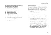
Class I .S. Connections for Simulating a 4 to Fluke 725Ex CCD Control Drawing when using in a non-Ex hazardous Area aly17f.eps 32 mA Transmitter in an Ex hazardous area. 725Ex Users Manual 725Ex MULTIFUNCTION PROCESS CALIBRATOR + Loop Power Supply Red V mA LOOP ZERO MEAS SOURCE STORE SETUP V mA TC RTD 2004.1573266 LR110460 Zone 0 AEx ia IIB 171 C I Div 1, Groups B,C,D RECALL Hz ˚C ˚F 100% 25% 25% 0% Black Readout or Controller - Figure 14. Refer to 20-
Class I .S. Connections for Simulating a 4 to Fluke 725Ex CCD Control Drawing when using in a non-Ex hazardous Area aly17f.eps 32 mA Transmitter in an Ex hazardous area. 725Ex Users Manual 725Ex MULTIFUNCTION PROCESS CALIBRATOR + Loop Power Supply Red V mA LOOP ZERO MEAS SOURCE STORE SETUP V mA TC RTD 2004.1573266 LR110460 Zone 0 AEx ia IIB 171 C I Div 1, Groups B,C,D RECALL Hz ˚C ˚F 100% 25% 25% 0% Black Readout or Controller - Figure 14. Refer to 20-

FE 725ex Users Manual
Page 43
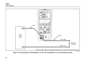
Electrical Sourcing Connections aly16f.eps 33 Red Black Using Source Mode 30V 24mA MAX ALL TERMINALS +mmAS+AOURCE / MEASURE V 3W TC Hz RTD MEASURE V mA LOOP mA- 4W COM COM Common V Hz + Device Under Test - Red 30V 24mA MAX ALL TERMINALS SOURCE / MEASURE mA+ 3W V TC Hz RTD MEASURE V mA LOOP mA- 4W COM COM Black Common Refer to Fluke 725Ex CCD Control Drawing when using in an Ex hazardous area. mA + - Figure 15.
Electrical Sourcing Connections aly16f.eps 33 Red Black Using Source Mode 30V 24mA MAX ALL TERMINALS +mmAS+AOURCE / MEASURE V 3W TC Hz RTD MEASURE V mA LOOP mA- 4W COM COM Common V Hz + Device Under Test - Red 30V 24mA MAX ALL TERMINALS SOURCE / MEASURE mA+ 3W V TC Hz RTD MEASURE V mA LOOP mA- 4W COM COM Black Common Refer to Fluke 725Ex CCD Control Drawing when using in an Ex hazardous area. mA + - Figure 15.
FE 725ex Users Manual
Page 45
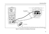
TC TC Miniplug Refer to Fluke 725Ex CCD Control Drawing when using in an Ex hazardous area. Figure 16. Connections for Simulating a Thermocouple aly20f.eps 35 Class I .S. Using Source Mode 725Ex MULTIFUNCTION PROCESS CALIBRATOR V mA LOOP ZERO MEAS SOURCE STORE SETUP V mA TC RTD 2004.1573266 LR110460 Zone 0 AEx ia IIB 171 C I Div 1, Groups B,C,D RECALL Hz ˚C ˚F 100% 25% 25% 0% Color depends on type of TC TEST DC PWR - ++ +-
TC TC Miniplug Refer to Fluke 725Ex CCD Control Drawing when using in an Ex hazardous area. Figure 16. Connections for Simulating a Thermocouple aly20f.eps 35 Class I .S. Using Source Mode 725Ex MULTIFUNCTION PROCESS CALIBRATOR V mA LOOP ZERO MEAS SOURCE STORE SETUP V mA TC RTD 2004.1573266 LR110460 Zone 0 AEx ia IIB 171 C I Div 1, Groups B,C,D RECALL Hz ˚C ˚F 100% 25% 25% 0% Color depends on type of TC TEST DC PWR - ++ +-

FE 725ex Users Manual
Page 46
Figure 17. Zone 0 Class I .S. Connections for Simulating 3-Wire RTD aly40f.eps 36 725Ex Users Manual 725Ex PMRUOLCTIEFSUSNCCTAIOLINBRATOR V mA LOOP ZERO MEAS SOURCE SSETTOURPE RECALL V mA TC RTD I ADEivLx21iR0a,01GII41rBo.01u14p75s167B0C3,2C,6D6 Hz ˚C ˚F 100% 25% 25% 0% Black Black Sensor Terminals 1 4 3 2 Red Refer to Fluke 725Ex CCD Control Drawing when using in an Ex hazardous area.
Figure 17. Zone 0 Class I .S. Connections for Simulating 3-Wire RTD aly40f.eps 36 725Ex Users Manual 725Ex PMRUOLCTIEFSUSNCCTAIOLINBRATOR V mA LOOP ZERO MEAS SOURCE SSETTOURPE RECALL V mA TC RTD I ADEivLx21iR0a,01GII41rBo.01u14p75s167B0C3,2C,6D6 Hz ˚C ˚F 100% 25% 25% 0% Black Black Sensor Terminals 1 4 3 2 Red Refer to Fluke 725Ex CCD Control Drawing when using in an Ex hazardous area.

FE 725ex Users Manual
Page 52
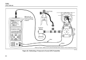
Calibrating a Thermocouple Transmitter aly44f.eps 42 Figure 19. Black Refer to Fluke 725Ex CCD Control Drawing when using in an Ex hazardous area. 725Ex Users Manual 725Ex MULTIFUNCTION PROCESS CALIBRATOR V mA LOOP ZERO MEAS SOURCE STORE SETUP V mA TC RTD 2004.1573266 LR110460 Zone 0 AEx ia IIB 171 C I Div 1, Groups B,C,D RECALL Hz ˚C ˚F 100% 25% 25% 0% Red TEST DC PWR - ++ - +- Class I .S.
Calibrating a Thermocouple Transmitter aly44f.eps 42 Figure 19. Black Refer to Fluke 725Ex CCD Control Drawing when using in an Ex hazardous area. 725Ex Users Manual 725Ex MULTIFUNCTION PROCESS CALIBRATOR V mA LOOP ZERO MEAS SOURCE STORE SETUP V mA TC RTD 2004.1573266 LR110460 Zone 0 AEx ia IIB 171 C I Div 1, Groups B,C,D RECALL Hz ˚C ˚F 100% 25% 25% 0% Red TEST DC PWR - ++ - +- Class I .S.
FE 725ex Users Manual
Page 54
Calibrating a Pressure-to-Current (P/I Div 1, Groups B,C,D RECALL Hz ˚C ˚F 100% 25% 25% 0% Pressure Module Red Black Refer to Fluke 725Ex CCD Control Drawing when using in an Ex hazardous area. 725Ex Users Manual 725Ex MULTIFUNCTION PROCESS CALIBRATOR Measure mA Source Pressure 12 V Loop Power Enabled Hand Pump SIGNAL + - Class I ) Transmitter aly34f.eps TEST 44 V mA LOOP ZERO MEAS SOURCE STORE SETUP V mA TC RTD 2004.1573266 LR110460 Zone 0 AEx ia IIB 171 C I.S. Figure 20.
Calibrating a Pressure-to-Current (P/I Div 1, Groups B,C,D RECALL Hz ˚C ˚F 100% 25% 25% 0% Pressure Module Red Black Refer to Fluke 725Ex CCD Control Drawing when using in an Ex hazardous area. 725Ex Users Manual 725Ex MULTIFUNCTION PROCESS CALIBRATOR Measure mA Source Pressure 12 V Loop Power Enabled Hand Pump SIGNAL + - Class I ) Transmitter aly34f.eps TEST 44 V mA LOOP ZERO MEAS SOURCE STORE SETUP V mA TC RTD 2004.1573266 LR110460 Zone 0 AEx ia IIB 171 C I.S. Figure 20.

FE 725ex Users Manual
Page 56
Figure 21. Class I /P) Transmitter aly28f.eps Calibrating a Current-to-Pressure (I Div 1, Groups B,C,D RECALL Hz ˚C ˚F 100% 25% 25% 0% Pressure Module Red Black Refer to Fluke 725Ex CCD Control Drawing when using in an Ex hazardous area. 725Ex Users Manual 725Ex MULTIFUNCTION PROCESS CALIBRATOR Measure Pressure Source mA SIGNAL + - TEST 46 V mA LOOP ZERO MEAS SOURCE STORE SETUP V mA TC RTD 2004.1573266 LR110460 Zone 0 AEx ia IIB 171 C I.S.
Figure 21. Class I /P) Transmitter aly28f.eps Calibrating a Current-to-Pressure (I Div 1, Groups B,C,D RECALL Hz ˚C ˚F 100% 25% 25% 0% Pressure Module Red Black Refer to Fluke 725Ex CCD Control Drawing when using in an Ex hazardous area. 725Ex Users Manual 725Ex MULTIFUNCTION PROCESS CALIBRATOR Measure Pressure Source mA SIGNAL + - TEST 46 V mA LOOP ZERO MEAS SOURCE STORE SETUP V mA TC RTD 2004.1573266 LR110460 Zone 0 AEx ia IIB 171 C I.S.

FE 725ex Users Manual
Page 58
... as follows: 1. If necessary, press for frequency or resistance (lower display). aly25f.eps Figure 22. 725Ex Users Manual Testing an Output Device Use the source functions to Fluke 725Ex CCD Control Drawing when using in Figure 22. 2. Press V for current or dc voltage, or F for SOURCE mode.... 48 725Ex MULTIFUNCTION PROCESS CALIBRATOR Red 0 to 1 V dc Input V mA LOOP ZERO MEAS SOURCE STORE SETUP V mA...
... as follows: 1. If necessary, press for frequency or resistance (lower display). aly25f.eps Figure 22. 725Ex Users Manual Testing an Output Device Use the source functions to Fluke 725Ex CCD Control Drawing when using in Figure 22. 2. Press V for current or dc voltage, or F for SOURCE mode.... 48 725Ex MULTIFUNCTION PROCESS CALIBRATOR Red 0 to 1 V dc Input V mA LOOP ZERO MEAS SOURCE STORE SETUP V mA...

FE 725ex Users Manual
Page 70
725Ex Users Manual Entity Parameters For Entity Parameters, Refer to Fluke 725Ex CCD, Control Drawing for use in Ex hazardous areas. 60
725Ex Users Manual Entity Parameters For Entity Parameters, Refer to Fluke 725Ex CCD, Control Drawing for use in Ex hazardous areas. 60