Fluke 51II, 52II, 53II, and 54II Thermometer Datasheet
Page 1
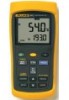
...54 II J,K,T,E,N,R,S Dual Time of Day ● Fluke 51 II Fluke 52 II Fluke 53 II Included Accessories Impact absorbing holster Two bead probe thermocouples 80PK-1 (54+52) One bead probe thermocouple 80PK-1 (51+53) Ordering Information Fluke 51 II Thermometer Fluke 52 II Thermometer Fluke 53 II Thermometer Fluke 54 II Thermometer... 0.50% + 0.3°C (0.5°F) ] **Only the Fluke Models 53 and 54 Series II thermometers are capable of measuring N, R, and S-type thermocouples. 50 Series II Thermometers Fluke 54 II Laboratory accuracy. Wherever you go. Battery life: 1000...
...54 II J,K,T,E,N,R,S Dual Time of Day ● Fluke 51 II Fluke 52 II Fluke 53 II Included Accessories Impact absorbing holster Two bead probe thermocouples 80PK-1 (54+52) One bead probe thermocouple 80PK-1 (51+53) Ordering Information Fluke 51 II Thermometer Fluke 52 II Thermometer Fluke 53 II Thermometer Fluke 54 II Thermometer... 0.50% + 0.3°C (0.5°F) ] **Only the Fluke Models 53 and 54 Series II thermometers are capable of measuring N, R, and S-type thermocouples. 50 Series II Thermometers Fluke 54 II Laboratory accuracy. Wherever you go. Battery life: 1000...

FE 53 & 54 II Users Manual
Page 1
Printed in USA All product names are trademarks of their respective companies. ® 53 & 54 Series II Thermometer Users Manual September 1999 Rev.1, 6/01 © 1999-2001 Fluke Corporation, All rights reserved.
Printed in USA All product names are trademarks of their respective companies. ® 53 & 54 Series II Thermometer Users Manual September 1999 Rev.1, 6/01 © 1999-2001 Fluke Corporation, All rights reserved.

FE 53 & 54 II Users Manual
Page 3
Table of Contents Title Page Safety Information...1 Contacting Fluke ...1 Getting Started...4 Components...5 Display Elements ...6 Buttons...7 Using the Thermometer 9 Changing Setup Options 9 Entering and Exiting Setup 9 Changing the Logging Interval 10 Changing the Thermocouple Type 11 Changing the Offset 11 Enabling or Disabling Sleep Mode 12 Setting the Time...12 Changing the Line Frequency 13 Measuring Temperatures 13 Connecting a Thermocouple 13 i
Table of Contents Title Page Safety Information...1 Contacting Fluke ...1 Getting Started...4 Components...5 Display Elements ...6 Buttons...7 Using the Thermometer 9 Changing Setup Options 9 Entering and Exiting Setup 9 Changing the Logging Interval 10 Changing the Thermocouple Type 11 Changing the Offset 11 Enabling or Disabling Sleep Mode 12 Setting the Time...12 Changing the Line Frequency 13 Measuring Temperatures 13 Connecting a Thermocouple 13 i

FE 53 & 54 II Users Manual
Page 4
53 & 54 Series II Users Manual Displaying Temperatures 14 Holding the Displayed Temperatures 14 Viewing the MIN, MAX, and AVG Readings 14 Using the Offset to Adjust ... Maintenance...19 Replacing the Batteries 19 Cleaning the Case and Holster 19 Calibration ...19 Specifications ...19 Environmental...19 General...20 80 PK-1 Thermocouple (supplied with thermometer 20 Electrical...20 Replacement Parts and Accessories 21 ii
53 & 54 Series II Users Manual Displaying Temperatures 14 Holding the Displayed Temperatures 14 Viewing the MIN, MAX, and AVG Readings 14 Using the Offset to Adjust ... Maintenance...19 Replacing the Batteries 19 Cleaning the Case and Holster 19 Calibration ...19 Specifications ...19 Environmental...19 General...20 80 PK-1 Thermocouple (supplied with thermometer 20 Electrical...20 Replacement Parts and Accessories 21 ii

FE 53 & 54 II Users Manual
Page 5
...-200 in Europe +81-3-3434-0181 in Japan +65-738-5655 in this manual. Use the thermometer only as temperature sensors. P.O. 53 & 54 Series II Safety Information The Fluke Model 53 and Model 54 Thermometers ("the thermometer") are microprocessor-based, digital thermometers designed to use external J-, K-, T-, E-, R-, S-, and N-type thermocouples (temperature probes) as specified in Singapore +1-425-446...
...-200 in Europe +81-3-3434-0181 in Japan +65-738-5655 in this manual. Use the thermometer only as temperature sensors. P.O. 53 & 54 Series II Safety Information The Fluke Model 53 and Model 54 Thermometers ("the thermometer") are microprocessor-based, digital thermometers designed to use external J-, K-, T-, E-, R-, S-, and N-type thermocouples (temperature probes) as specified in Singapore +1-425-446...
FE 53 & 54 II Users Manual
Page 6
...thermometer if it operates abnormally. Protection may be impaired. When in doubt, have the thermometer serviced. • Do not operate the thermometer around the connectors. • Disconnect the thermocouple(s) from the thermometer... before opening the case. • Replace the batteries as soon as marked on the thermometer...follow these guidelines: • Before using the thermometer inspect the case. Safety Information WWarning A Warning...
...thermometer if it operates abnormally. Protection may be impaired. When in doubt, have the thermometer serviced. • Do not operate the thermometer around the connectors. • Disconnect the thermocouple(s) from the thermometer... before opening the case. • Replace the batteries as soon as marked on the thermometer...follow these guidelines: • Before using the thermometer inspect the case. Safety Information WWarning A Warning...

FE 53 & 54 II Users Manual
Page 7
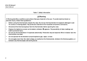
...between the two thermocouples. Table 1. Safety Information (cont.) 53 & 54 Series II Safety Information WWarning (cont.) • Model 54: Measurement errors may damage the meter or the equipment under test. • Use the proper thermocouples, function, and range for your thermometer. • Do not attempt to recharge the batteries. •...if voltages on the measurement surfaces result in potentials greater than 1 V between the thermocouples, use electrically insulated thermocouples. • When servicing the thermometer, use only specified replacement parts. • Do not use the...
...between the two thermocouples. Table 1. Safety Information (cont.) 53 & 54 Series II Safety Information WWarning (cont.) • Model 54: Measurement errors may damage the meter or the equipment under test. • Use the proper thermocouples, function, and range for your thermometer. • Do not attempt to recharge the batteries. •...if voltages on the measurement surfaces result in potentials greater than 1 V between the thermocouples, use electrically insulated thermocouples. • When servicing the thermometer, use only specified replacement parts. • Do not use the...

FE 53 & 54 II Users Manual
Page 8
Complies with the thermometer, study the following sections. 4 Then read the following : • Figure 1 and Table 3 describe the components. • Figure 2 and Table 4 describe the display. • Table 5 describes the functions of the buttons. International Symbols W Refer to Models 53 and 54 unless otherwise indicated. 53 & 54 Series II Users Manual Table 2. To become...
Complies with the thermometer, study the following sections. 4 Then read the following : • Figure 1 and Table 3 describe the components. • Figure 2 and Table 4 describe the display. • Table 5 describes the functions of the buttons. International Symbols W Refer to Models 53 and 54 unless otherwise indicated. 53 & 54 Series II Users Manual Table 2. To become...

FE 53 & 54 II Users Manual
Page 11
Q Press Q to turn the thermometer on and off after 2 minutes without any button presses. M Press M to stop displaying the minimum, maximum, and average readings in the secondary display. Buttons A Press A ...) to toggle the IR port on and off this display. C When viewing logged readings, shows the maximum, minimum, and average of the logged readings. 53 & 54 Series II Getting Started Buttons Table 5. Press G, J (CLEAR MEMORY) to switch between Celsius (oC), Fahrenheit (oF), and Kelvin (K). 7 The backlight turns off . Press C to delete...
Q Press Q to turn the thermometer on and off after 2 minutes without any button presses. M Press M to stop displaying the minimum, maximum, and average readings in the secondary display. Buttons A Press A ...) to toggle the IR port on and off this display. C When viewing logged readings, shows the maximum, minimum, and average of the logged readings. 53 & 54 Series II Getting Started Buttons Table 5. Press G, J (CLEAR MEMORY) to switch between Celsius (oC), Fahrenheit (oF), and Kelvin (K). 7 The backlight turns off . Press C to delete...

FE 53 & 54 II Users Manual
Page 12
...Setup option you want to toggle showing the T1, T2, and T1-T2 (differential temperature measurement) in memory. Model 54: Press T to change . During manual logging, the thermometer stores a single set of logged readings in memory each time you want to start or stop . 8 53... & 54 Series II Users Manual h T D K N E J r Table 5. Press D to change . Press N to scroll to test the display. Press r again to enter a ...
...Setup option you want to toggle showing the T1, T2, and T1-T2 (differential temperature measurement) in memory. Model 54: Press T to change . During manual logging, the thermometer stores a single set of logged readings in memory each time you want to start or stop . 8 53... & 54 Series II Users Manual h T D K N E J r Table 5. Press D to change . Press N to scroll to test the display. Press r again to enter a ...

FE 53 & 54 II Users Manual
Page 13
... the first reading. Setup settings reset only when the batteries are removed for more than 2 minutes. 53 & 54 Series II Using the Thermometer Entering and Exiting Setup When the thermometer is "open," the display shows "- - - -." Plug the thermocouple(s) into the selected input or the thermocouple is in Setup mode, the ... the setup option you want to start or exit Setup. Press A to change . Setup is plugged into the input connector(s). 2. Using the Thermometer 1. Changing Setup Options Use Setup to turn on the thermometer. If no thermocouple is disabled in its memory.
... the first reading. Setup settings reset only when the batteries are removed for more than 2 minutes. 53 & 54 Series II Using the Thermometer Entering and Exiting Setup When the thermometer is "open," the display shows "- - - -." Plug the thermocouple(s) into the selected input or the thermocouple is in Setup mode, the ... the setup option you want to start or exit Setup. Press A to change . Setup is plugged into the input connector(s). 2. Using the Thermometer 1. Changing Setup Options Use Setup to turn on the thermometer. If no thermocouple is disabled in its memory.

FE 53 & 54 II Users Manual
Page 14
53 & 54 Series II Users Manual Changing the Logging Interval The logging interval determines how often the thermometer stores logged readings in memory. 1. If you selected a user-defined logging interval: • Press K or N until the right two digits you want appear on the...the display shows the logging interval you want appear on the display, and then press E to select them . The left two digits you press J, the thermometer stores the current readings in memory. You can select a logging interval of the logging interval. Press E to change more quickly. 10 You can also set...
53 & 54 Series II Users Manual Changing the Logging Interval The logging interval determines how often the thermometer stores logged readings in memory. 1. If you selected a user-defined logging interval: • Press K or N until the right two digits you want appear on the...the display shows the logging interval you want appear on the display, and then press E to select them . The left two digits you press J, the thermometer stores the current readings in memory. You can select a logging interval of the logging interval. Press E to change more quickly. 10 You can also set...

FE 53 & 54 II Users Manual
Page 15
... is ± 5.0 oC or K, and ± 9.0 oF. Press K or N until the display shows TYPE. 2. The temperature measurement plus the offset appears in memory. 53 & 54 Series II Changing Setup Options Changing the Offset You can store individual offsets for Probe Errors." The offset appears in memory. Remember to reset the... appears on the display. 4. The currently selected thermocouple blinks. 3. The offset automatically resets to Adjust for T1 and T2. 1. Changing the Thermocouple Type 1. Model 54: You can adjust the thermometer's readings to display the thermocouple type choices.
... is ± 5.0 oC or K, and ± 9.0 oF. Press K or N until the display shows TYPE. 2. The temperature measurement plus the offset appears in memory. 53 & 54 Series II Changing Setup Options Changing the Offset You can store individual offsets for Probe Errors." The offset appears in memory. Remember to reset the... appears on the display. 4. The currently selected thermocouple blinks. 3. The offset automatically resets to Adjust for T1 and T2. 1. Changing the Thermocouple Type 1. Model 54: You can adjust the thermometer's readings to display the thermocouple type choices.

FE 53 & 54 II Users Manual
Page 16
...-hour format), and then press E to change the sleep setting. Press K or N until the display shows on or 0FF. 4. Pressing any button wakes the thermometer and returns it is off. 3. Press E to store the time in memory. Press K or N as needed until the display shows the correct minutes, and ...then press E to store the sleep setting in memory. The right two digits blink. 4. 53 & 54 Series II Users Manual Enabling or Disabling Sleep Mode The thermometer enters sleep mode if no button press occurs for 20 minutes. Press E to indicate that you want to set or...
...-hour format), and then press E to change the sleep setting. Press K or N until the display shows on or 0FF. 4. Pressing any button wakes the thermometer and returns it is off. 3. Press E to store the time in memory. Press K or N as needed until the display shows the correct minutes, and ...then press E to store the sleep setting in memory. The right two digits blink. 4. 53 & 54 Series II Users Manual Enabling or Disabling Sleep Mode The thermometer enters sleep mode if no button press occurs for 20 minutes. Press E to indicate that you want to set or...

FE 53 & 54 II Users Manual
Page 17
...60 V (50 Hz or 60 Hz). 4. Press E to indicate that you want to store the line setting in memory. 53 & 54 Series II Measuring Temperatures Measuring Temperatures Connecting a Thermocouple Thermocouples are color coded by type based on the North American ANSI Color Code: Type ...Color Type Color J Black R Green K Yellow S Green T Blue N Orange E Purple 1. Set the thermometer for the local line frequency as needed until the display shows Li ne. 2. Plug a thermocouple into the input connector(s). 2. Press E to change the...
...60 V (50 Hz or 60 Hz). 4. Press E to indicate that you want to store the line setting in memory. 53 & 54 Series II Measuring Temperatures Measuring Temperatures Connecting a Thermocouple Thermocouples are color coded by type based on the North American ANSI Color Code: Type ...Color Type Color J Black R Green K Yellow S Green T Blue N Orange E Purple 1. Set the thermometer for the local line frequency as needed until the display shows Li ne. 2. Plug a thermocouple into the input connector(s). 2. Press E to change the...

FE 53 & 54 II Users Manual
Page 19
... the offset until the primary display reading matches the calibration temperature. (See "Changing Setup Options.") 53 & 54 Series II Using Memory Using Memory During a logging session the thermometer stores logged readings in Setup to adjust the thermometer's readings to compensate for the errors of the logging session you can view the logged readings...
... the offset until the primary display reading matches the calibration temperature. (See "Changing Setup Options.") 53 & 54 Series II Using Memory Using Memory During a logging session the thermometer stores logged readings in Setup to adjust the thermometer's readings to compensate for the errors of the logging session you can view the logged readings...

FE 53 & 54 II Users Manual
Page 20
...interval. (See "Changing Setup Options.") 2. If you want to start logging. The display shows l. 3. Press J to store logged readings in FlukeView Forms. The thermometer has 500 memory locations. It stores 250 sets of temperature readings and 250 sets of initial conditions when logging continuously. 53...Starting and Stopping Logging Setup, memory clear, and PC communications are a time stamp, the T1 reading, and the T2 and T1-T2 readings (Model 54). The thermometer stores 499 sets of temperature readings and one set of initial conditions when logging individual points manually.
...interval. (See "Changing Setup Options.") 2. If you want to start logging. The display shows l. 3. Press J to store logged readings in FlukeView Forms. The thermometer has 500 memory locations. It stores 250 sets of temperature readings and 250 sets of initial conditions when logging continuously. 53...Starting and Stopping Logging Setup, memory clear, and PC communications are a time stamp, the T1 reading, and the T2 and T1-T2 readings (Model 54). The thermometer stores 499 sets of temperature readings and one set of initial conditions when logging individual points manually.

FE 53 & 54 II Users Manual
Page 22
... 1:49 P.M. Press r to step through the minimum, maximum, average, and current logged reading. Note The thermometer calculates the minimum and maximum of the thermometer's memory to satisfy ISO-9000 documentation requirements. FlukeView Forms places the logged readings into standard (default) or customized... to a PC using FlukeView Forms. The communication requires an IR (infrared) serial connection. Communicating with FlukeView Forms. 18 53 & 54 Series II Users Manual 3. For example, Figure 4 shows the maximum reading in memory location 5. You can transfer the contents of ...
... 1:49 P.M. Press r to step through the minimum, maximum, average, and current logged reading. Note The thermometer calculates the minimum and maximum of the thermometer's memory to satisfy ISO-9000 documentation requirements. FlukeView Forms places the logged readings into standard (default) or customized... to a PC using FlukeView Forms. The communication requires an IR (infrared) serial connection. Communicating with FlukeView Forms. 18 53 & 54 Series II Users Manual 3. For example, Figure 4 shows the maximum reading in memory location 5. You can transfer the contents of ...

FE 53 & 54 II Users Manual
Page 23
... and water or a mild commercial cleaner. To calibrate the thermometer, contact Fluke for the Service Center nearest you calibrate the thermometer annually, starting one year after purchase. Wipe with a damp sponge or soft rag. 53 & 54 Series II Maintenance Calibration To ensure that the thermometer performs to +140 oF) Humidity Non condensing Turn off the...
... and water or a mild commercial cleaner. To calibrate the thermometer, contact Fluke for the Service Center nearest you calibrate the thermometer annually, starting one year after purchase. Wipe with a damp sponge or soft rag. 53 & 54 Series II Maintenance Calibration To ensure that the thermometer performs to +140 oF) Humidity Non condensing Turn off the...

FE 53 & 54 II Users Manual
Page 24
and S-type: 0 oC to +1767 oC (+32 oF to an appropriate low level. Equipment of Impulse Withstand Voltage protection provided. 53 & 54 Series II Users Manual General Weight 280 g (10 oz) Dimensions (without holster) 2.8 cm × 7.8 cm × 16.2 cm (1.1 in × 3 in &#...to +3212 oF) 0.1 oC / oF / K < 1000o 1.0 oC / oF / K ≥ 1000o Example include protect electronic circuits. 20 80 PK-1 Thermocouple (supplied with thermometer) Type Temperature Range Accuracy Type K, Chromel Alumel, bead style −40 oC to +260 oC (−40 oF to +500 oF) ± 1.1 oC (± 2.0 ...
and S-type: 0 oC to +1767 oC (+32 oF to an appropriate low level. Equipment of Impulse Withstand Voltage protection provided. 53 & 54 Series II Users Manual General Weight 280 g (10 oz) Dimensions (without holster) 2.8 cm × 7.8 cm × 16.2 cm (1.1 in × 3 in &#...to +3212 oF) 0.1 oC / oF / K < 1000o 1.0 oC / oF / K ≥ 1000o Example include protect electronic circuits. 20 80 PK-1 Thermocouple (supplied with thermometer) Type Temperature Range Accuracy Type K, Chromel Alumel, bead style −40 oC to +260 oC (−40 oF to +500 oF) ± 1.1 oC (± 2.0 ...

