Fluke 51II, 52II, 53II, and 54II Thermometer Datasheet
Page 1
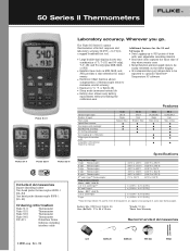
... Time of Day ● ● ● ● ● ● 54 II J,K,T,E,N,R,S Dual Time of Day ● Fluke 51 II Fluke 52 II Fluke 53 II Included Accessories Impact absorbing holster Two bead probe thermocouples 80PK-1 (54+52) One bead probe thermocouple 80PK-1 (51+53) Ordering Information Fluke 51 II Thermometer Fluke 52 II Thermometer Fluke 53 II Thermometer Fluke 54 II Thermometer FVF-SC1 FlukeView Forms Software including interface cable Specifi...
... Time of Day ● ● ● ● ● ● 54 II J,K,T,E,N,R,S Dual Time of Day ● Fluke 51 II Fluke 52 II Fluke 53 II Included Accessories Impact absorbing holster Two bead probe thermocouples 80PK-1 (54+52) One bead probe thermocouple 80PK-1 (51+53) Ordering Information Fluke 51 II Thermometer Fluke 52 II Thermometer Fluke 53 II Thermometer Fluke 54 II Thermometer FVF-SC1 FlukeView Forms Software including interface cable Specifi...

FE 53 & 54 II Users Manual
Page 1
Printed in USA All product names are trademarks of their respective companies. ® 53 & 54 Series II Thermometer Users Manual September 1999 Rev.1, 6/01 © 1999-2001 Fluke Corporation, All rights reserved.
Printed in USA All product names are trademarks of their respective companies. ® 53 & 54 Series II Thermometer Users Manual September 1999 Rev.1, 6/01 © 1999-2001 Fluke Corporation, All rights reserved.

FE 53 & 54 II Users Manual
Page 4
53 & 54 Series II Users Manual Displaying Temperatures 14 Holding the Displayed Temperatures 14 Viewing the MIN, MAX, and AVG Readings 14 Using the Offset to Adjust for Probe ... Maintenance...19 Replacing the Batteries 19 Cleaning the Case and Holster 19 Calibration ...19 Specifications ...19 Environmental...19 General...20 80 PK-1 Thermocouple (supplied with thermometer 20 Electrical...20 Replacement Parts and Accessories 21...
53 & 54 Series II Users Manual Displaying Temperatures 14 Holding the Displayed Temperatures 14 Viewing the MIN, MAX, and AVG Readings 14 Using the Offset to Adjust for Probe ... Maintenance...19 Replacing the Batteries 19 Cleaning the Case and Holster 19 Calibration ...19 Specifications ...19 Environmental...19 General...20 80 PK-1 Thermocouple (supplied with thermometer 20 Electrical...20 Replacement Parts and Accessories 21...

FE 53 & 54 II Users Manual
Page 5
... from other countries Address correspondence to use external J-, K-, T-, E-, R-, S-, and N-type thermocouples (temperature probes) as specified in Table 2. 53 & 54 Series II Safety Information The Fluke Model 53 and Model 54 Thermometers ("the thermometer") are microprocessor-based, digital thermometers designed to : Fluke Corporation P.O. Box 1186 5602 BD Eindhoven The Netherlands Visit us on the World Wide Web at: www...
... from other countries Address correspondence to use external J-, K-, T-, E-, R-, S-, and N-type thermocouples (temperature probes) as specified in Table 2. 53 & 54 Series II Safety Information The Fluke Model 53 and Model 54 Thermometers ("the thermometer") are microprocessor-based, digital thermometers designed to : Fluke Corporation P.O. Box 1186 5602 BD Eindhoven The Netherlands Visit us on the World Wide Web at: www...
FE 53 & 54 II Users Manual
Page 6
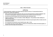
...54 Series II Users Manual Table 1. Pay particular attention to the insulation around explosive gas, vapor, or dust. • Do not apply more than the rated voltage, as the battery indicator (B) appears. The possibility of false readings can lead to the user. Do not use the thermometer... if it appears damaged. When in doubt, have the thermometer serviced. • Do not operate the thermometer around the connectors. • Disconnect the thermocouple(s) from the thermometer before opening the case. • Replace the ...
...54 Series II Users Manual Table 1. Pay particular attention to the insulation around explosive gas, vapor, or dust. • Do not apply more than the rated voltage, as the battery indicator (B) appears. The possibility of false readings can lead to the user. Do not use the thermometer... if it appears damaged. When in doubt, have the thermometer serviced. • Do not operate the thermometer around the connectors. • Disconnect the thermocouple(s) from the thermometer before opening the case. • Replace the ...

FE 53 & 54 II Users Manual
Page 7
... differences are anticipated between the two thermocouples. Safety Information (cont.) 53 & 54 Series II Safety Information WWarning (cont.) • Model 54: Measurement errors may damage the meter or the equipment under test. • Use the proper thermocouples, function, and range for your thermometer. • Do not attempt to recharge the batteries. • To prevent...
... differences are anticipated between the two thermocouples. Safety Information (cont.) 53 & 54 Series II Safety Information WWarning (cont.) • Model 54: Measurement errors may damage the meter or the equipment under test. • Use the proper thermocouples, function, and range for your thermometer. • Do not attempt to recharge the batteries. • To prevent...

FE 53 & 54 II Users Manual
Page 8
P Complies with relevant Canadian Standards Association directives. To become familiar with the thermometer, study the following sections. 4 International Symbols W Refer to Models 53 and 54 unless otherwise indicated. M Battery. Then read the following : • Figure 1 and Table 3 describe the...• Figure 2 and Table 4 describe the display. • Table 5 describes the functions of the buttons. 53 & 54 Series II Users Manual Table 2. Complies with European Union directives. Getting Started Everything in this Users Manual applies both to the manual for ...
P Complies with relevant Canadian Standards Association directives. To become familiar with the thermometer, study the following sections. 4 International Symbols W Refer to Models 53 and 54 unless otherwise indicated. M Battery. Then read the following : • Figure 1 and Table 3 describe the...• Figure 2 and Table 4 describe the display. • Table 5 describes the functions of the buttons. 53 & 54 Series II Users Manual Table 2. Complies with European Union directives. Getting Started Everything in this Users Manual applies both to the manual for ...

FE 53 & 54 II Users Manual
Page 11
... through the maximum, minimum, and average readings. C When viewing logged readings, shows the maximum, minimum, and average of the logged readings. M Press M to turn the thermometer on and off . 53 & 54 Series II Getting Started Buttons Table 5.
... through the maximum, minimum, and average readings. C When viewing logged readings, shows the maximum, minimum, and average of the logged readings. M Press M to turn the thermometer on and off . 53 & 54 Series II Getting Started Buttons Table 5.

FE 53 & 54 II Users Manual
Page 12
53 & 54 Series II Users Manual h T D K N E J r Table 5. Press J to enter a Setup option. Press E to start or exit Setup. (See "Changing Setup Options.") Press K to scroll to the Setup option you want to change . Press r to show logged readings and MIN MAX readings on the thermometer to test...display. Press h when turning on the display. Press D to start or stop . 8 During manual logging, the thermometer stores a single set of logged readings in memory. Model 54: Press T to stop logging. Press r again to toggle showing the T1, T2, and T1-T2 (differential temperature...
53 & 54 Series II Users Manual h T D K N E J r Table 5. Press J to enter a Setup option. Press E to start or exit Setup. (See "Changing Setup Options.") Press K to scroll to the Setup option you want to change . Press r to show logged readings and MIN MAX readings on the thermometer to test...display. Press h when turning on the display. Press D to start or stop . 8 During manual logging, the thermometer stores a single set of logged readings in memory. Model 54: Press T to stop logging. Press r again to toggle showing the T1, T2, and T1-T2 (differential temperature...

FE 53 & 54 II Users Manual
Page 13
...Setup. Setup settings reset only when the batteries are removed for more than 2 minutes. 53 & 54 Series II Using the Thermometer Entering and Exiting Setup When the thermometer is "open," the display shows "- - - -." The thermometer stores the settings in Setup mode, the display shows s. • Press D to change the logging...into the selected input or the thermocouple is in its memory. Changing Setup Options Use Setup to turn on the thermometer. Using the Thermometer 1. Setup is plugged into the input connector(s). 2. If no thermocouple is disabled in MIN MAX mode. 9
...Setup. Setup settings reset only when the batteries are removed for more than 2 minutes. 53 & 54 Series II Using the Thermometer Entering and Exiting Setup When the thermometer is "open," the display shows "- - - -." The thermometer stores the settings in Setup mode, the display shows s. • Press D to change the logging...into the selected input or the thermocouple is in its memory. Changing Setup Options Use Setup to turn on the thermometer. Using the Thermometer 1. Setup is plugged into the input connector(s). 2. If no thermocouple is disabled in MIN MAX mode. 9

FE 53 & 54 II Users Manual
Page 14
...until the display shows hour:min or min:sec, and then press E to select. 4. 53 & 54 Series II Users Manual Changing the Logging Interval The logging interval determines how often the thermometer stores logged readings in memory. 1. Press E to change more quickly. 10 The right two digits ...select a logging interval of 1 second (1), 10 seconds (2), 1 minute (3), 10 minutes (4), or user-defined (USef). If you press J, the thermometer stores the current readings in memory. Each time you selected a user-defined logging interval: • Press K or N until the display shows INTERVAL. 2. ...
...until the display shows hour:min or min:sec, and then press E to select. 4. 53 & 54 Series II Users Manual Changing the Logging Interval The logging interval determines how often the thermometer stores logged readings in memory. 1. Press E to change more quickly. 10 The right two digits ...select a logging interval of 1 second (1), 10 seconds (2), 1 minute (3), 10 minutes (4), or user-defined (USef). If you press J, the thermometer stores the current readings in memory. Each time you selected a user-defined logging interval: • Press K or N until the display shows INTERVAL. 2. ...

FE 53 & 54 II Users Manual
Page 15
... setting. See "Using the Offset to store the offset setting in memory. 53 & 54 Series II Changing Setup Options Changing the Offset You can store individual offsets for the errors of a specific thermocouple. Model 54: You can adjust the thermometer's readings to store the thermocouple type in memory. The temperature measurement plus the offset...
... setting. See "Using the Offset to store the offset setting in memory. 53 & 54 Series II Changing Setup Options Changing the Offset You can store individual offsets for the errors of a specific thermocouple. Model 54: You can adjust the thermometer's readings to store the thermocouple type in memory. The temperature measurement plus the offset...

FE 53 & 54 II Users Manual
Page 16
53 & 54 Series II Users Manual Enabling or Disabling Sleep Mode The thermometer enters sleep mode if no button press occurs for 20 minutes. Sleep... shows the time if it to its previous state. 1. The right two digits blink. 4. Pressing any button wakes the thermometer and returns it is off. 3. Press K or N as needed until the display shows the correct minutes, and then ...press E to change more quickly. 12 Press E to indicate you turn on the thermometer and is enabled each time you want to store the time in memory. Press K or N until the display...
53 & 54 Series II Users Manual Enabling or Disabling Sleep Mode The thermometer enters sleep mode if no button press occurs for 20 minutes. Sleep... shows the time if it to its previous state. 1. The right two digits blink. 4. Pressing any button wakes the thermometer and returns it is off. 3. Press K or N as needed until the display shows the correct minutes, and then ...press E to change more quickly. 12 Press E to indicate you turn on the thermometer and is enabled each time you want to store the time in memory. Press K or N until the display...

FE 53 & 54 II Users Manual
Page 17
Press K or N as follows: 1. Changing the Line Frequency For optimum rejection of line noise, set the thermometer for the correct thermocouple type. Press E to indicate that you want to store the line setting in memory. 53 & 54 Series II Measuring Temperatures Measuring Temperatures Connecting a Thermocouple Thermocouples are color coded by type based on the...
Press K or N as follows: 1. Changing the Line Frequency For optimum rejection of line noise, set the thermometer for the correct thermocouple type. Press E to indicate that you want to store the line setting in memory. 53 & 54 Series II Measuring Temperatures Measuring Temperatures Connecting a Thermocouple Thermocouples are color coded by type based on the...

FE 53 & 54 II Users Manual
Page 19
... the offset until the primary display reading matches the calibration temperature. (See "Changing Setup Options.") 53 & 54 Series II Using Memory Using Memory During a logging session the thermometer stores logged readings in Setup to adjust the thermometer's readings to compensate for the errors of the logging session you can view the logged readings on...
... the offset until the primary display reading matches the calibration temperature. (See "Changing Setup Options.") 53 & 54 Series II Using Memory Using Memory During a logging session the thermometer stores logged readings in Setup to adjust the thermometer's readings to compensate for the errors of the logging session you can view the logged readings on...

FE 53 & 54 II Users Manual
Page 20
...using FlukeView Forms. The data entries are a time stamp, the T1 reading, and the T2 and T1-T2 readings (Model 54). The thermometer stores 499 sets of temperature readings and one set of initial conditions when logging individual points manually. It stores 250 sets of...16 Set the logging interval. (See "Changing Setup Options.") 2. If you selected a manual logging interval, press J each thermocouple input. 53 & 54 Series II Users Manual Initial Conditions and Data Entries Logged readings include initial conditions and data entries. Press J to stop logging. 4. Press J again to start...
...using FlukeView Forms. The data entries are a time stamp, the T1 reading, and the T2 and T1-T2 readings (Model 54). The thermometer stores 499 sets of temperature readings and one set of initial conditions when logging individual points manually. It stores 250 sets of...16 Set the logging interval. (See "Changing Setup Options.") 2. If you selected a manual logging interval, press J each thermocouple input. 53 & 54 Series II Users Manual Initial Conditions and Data Entries Logged readings include initial conditions and data entries. Press J to stop logging. 4. Press J again to start...

FE 53 & 54 II Users Manual
Page 22
...IR SEND) to stop viewing logged readings. The display shows: if Send When the IR port is empty. Note The thermometer calculates the minimum and maximum of the thermometer's memory to satisfy ISO-9000 documentation requirements. For example, Figure 4 shows the maximum reading in memory. The maximum ...comments. When you can use these forms to a PC using FlukeView Forms. The communication requires an IR (infrared) serial connection. 53 & 54 Series II Users Manual 3. and was stored in memory location 5. Press r to toggle the IR port on and off. Communicating with FlukeView Forms....
...IR SEND) to stop viewing logged readings. The display shows: if Send When the IR port is empty. Note The thermometer calculates the minimum and maximum of the thermometer's memory to satisfy ISO-9000 documentation requirements. For example, Figure 4 shows the maximum reading in memory. The maximum ...comments. When you can use these forms to a PC using FlukeView Forms. The communication requires an IR (infrared) serial connection. 53 & 54 Series II Users Manual 3. and was stored in memory location 5. Press r to toggle the IR port on and off. Communicating with FlukeView Forms....

FE 53 & 54 II Users Manual
Page 23
... remove the battery door. 3. Wipe with a damp sponge or soft rag. 53 & 54 Series II Maintenance Calibration To ensure that the thermometer performs to its accuracy specifications, Fluke recommends that you or follow the calibration procedure in the service manual listed in Table 1 ... door and tighten the screw. To calibrate the thermometer, contact Fluke for the Service Center nearest you calibrate the thermometer annually, starting one year after purchase. Replace the three AA batteries. 4. Turn off the thermometer if necessary. 2. Maintenance Replacing the Batteries Refer ...
... remove the battery door. 3. Wipe with a damp sponge or soft rag. 53 & 54 Series II Maintenance Calibration To ensure that the thermometer performs to its accuracy specifications, Fluke recommends that you or follow the calibration procedure in the service manual listed in Table 1 ... door and tighten the screw. To calibrate the thermometer, contact Fluke for the Service Center nearest you calibrate the thermometer annually, starting one year after purchase. Replace the three AA batteries. 4. Turn off the thermometer if necessary. 2. Maintenance Replacing the Batteries Refer ...

FE 53 & 54 II Users Manual
Page 24
53 & 54 Series II Users Manual General Weight 280 g (10 oz) Dimensions (without holster) 2.8 cm × 7.8 cm × 16.2 cm (1.1 in × 3 in × 6.4 in) Battery Certification 3 AA batteries P, s ... appropriate low level. and S-type: 0 oC to +1767 oC (+32 oF to +2372 oF) R- Example include protect electronic circuits. 20 80 PK-1 Thermocouple (supplied with thermometer) Type Temperature Range Accuracy Type K, Chromel Alumel, bead style −40 oC to +260 oC (−40 oF to +500 oF) ± 1.1 oC (± 2.0 oF...
53 & 54 Series II Users Manual General Weight 280 g (10 oz) Dimensions (without holster) 2.8 cm × 7.8 cm × 16.2 cm (1.1 in × 3 in × 6.4 in) Battery Certification 3 AA batteries P, s ... appropriate low level. and S-type: 0 oC to +1767 oC (+32 oF to +2372 oF) R- Example include protect electronic circuits. 20 80 PK-1 Thermocouple (supplied with thermometer) Type Temperature Range Accuracy Type K, Chromel Alumel, bead style −40 oC to +260 oC (−40 oF to +500 oF) ± 1.1 oC (± 2.0 oF...

