FE 51 & 52 II Users Manual
Page 1
® 51 & 52 Series II Thermometer English September 1999 Rev.1, 6/01 © 1999-2001 Fluke Corporation, All rights reserved. Users Manual Printed in USA All product names are trademarks of their respective companies.
® 51 & 52 Series II Thermometer English September 1999 Rev.1, 6/01 © 1999-2001 Fluke Corporation, All rights reserved. Users Manual Printed in USA All product names are trademarks of their respective companies.
FE 51 & 52 II Users Manual
Page 4
51 & 52 Series II Users Manual Maintenance...13 Replacing the Batteries 13 Cleaning the Case and Holster 13 Calibration ...13 Specifications ...13 Environmental...13 General...14 80 PK-1 Thermocouple (supplied with thermometer 14 Electrical...14 Replacement Parts and Accessories 15 ii
51 & 52 Series II Users Manual Maintenance...13 Replacing the Batteries 13 Cleaning the Case and Holster 13 Calibration ...13 Specifications ...13 Environmental...13 General...14 80 PK-1 Thermocouple (supplied with thermometer 14 Electrical...14 Replacement Parts and Accessories 15 ii
FE 51 & 52 II Users Manual
Page 5
... J-, K-, T-, and Etype thermocouples (temperature probes) as specified in Table 2. P.O. 51 & 52 Series II Introduction The Fluke Model 51 and Model 52 Thermometers ("the thermometer") are microprocessor-based, digital thermometers designed to : Fluke Corporation P.O. Refer to safety information in Table 1 and meter symbols in this manual. Box 1186 5602 BD Eindhoven The Netherlands Visit us on the...
... J-, K-, T-, and Etype thermocouples (temperature probes) as specified in Table 2. P.O. 51 & 52 Series II Introduction The Fluke Model 51 and Model 52 Thermometers ("the thermometer") are microprocessor-based, digital thermometers designed to : Fluke Corporation P.O. Refer to safety information in Table 1 and meter symbols in this manual. Box 1186 5602 BD Eindhoven The Netherlands Visit us on the...
FE 51 & 52 II Users Manual
Page 6
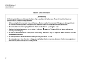
... abnormally. The possibility of false readings can lead to the user. Do not use the thermometer if it appears damaged. Protection may be impaired. 51 & 52 Series II Users Manual Table 1.
... abnormally. The possibility of false readings can lead to the user. Do not use the thermometer if it appears damaged. Protection may be impaired. 51 & 52 Series II Users Manual Table 1.
FE 51 & 52 II Users Manual
Page 8
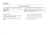
Battery. Getting Started Everything in this feature. 51 & 52 Series II Users Manual Table 2. Complies with European Union directives. To become familiar with the thermometer, study the following sections. 4 P Complies with relevant Canadian Standards Association directives. Then ... and Table 3 describe the components. • Figure 2 and Table 4 describe the display. • Table 5 describes the functions of the buttons. International Symbols W M Refer to the manual for information about this Users Manual applies both to Models 51 and 52 unless otherwise indicated.
Battery. Getting Started Everything in this feature. 51 & 52 Series II Users Manual Table 2. Complies with European Union directives. To become familiar with the thermometer, study the following sections. 4 P Complies with relevant Canadian Standards Association directives. Then ... and Table 3 describe the components. • Figure 2 and Table 4 describe the display. • Table 5 describes the functions of the buttons. International Symbols W M Refer to the manual for information about this Users Manual applies both to Models 51 and 52 unless otherwise indicated.
FE 51 & 52 II Users Manual
Page 10
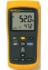
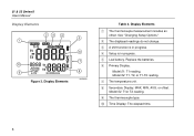
Display Elements xx 5 6 7 8 aas02f.eps Table 4. C A shift function is in progress. Model 52: T1, T2, or T1-T2 reading. 51 & 52 Series II Users Manual Display Elements 23 4 1 10 9 Figure 2. H Secondary Display: MAX, MIN, AVG, or offset. See "Changing Setup Options." D Setup is in progress. F Primary Display. I The thermocouple type. B ...
Display Elements xx 5 6 7 8 aas02f.eps Table 4. C A shift function is in progress. Model 52: T1, T2, or T1-T2 reading. 51 & 52 Series II Users Manual Display Elements 23 4 1 10 9 Figure 2. H Secondary Display: MAX, MIN, AVG, or offset. See "Changing Setup Options." D Setup is in progress. F Primary Display. I The thermocouple type. B ...
FE 51 & 52 II Users Manual
Page 12
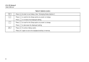
51 & 52 Series II Users Manual D K N E Table 5. Press N to change . Press N to scroll to the Setup option you want to decrease the displayed setting. Press E to change . Buttons (cont.) Press D to start or exit Setup. (See "Changing Setup Options.") Press K to scroll to the Setup option you want to enter a Setup option. Press K to store the displayed setting in memory. 8 Press E again to increase the displayed setting.
51 & 52 Series II Users Manual D K N E Table 5. Press N to change . Press N to scroll to the Setup option you want to decrease the displayed setting. Press E to change . Buttons (cont.) Press D to start or exit Setup. (See "Changing Setup Options.") Press K to scroll to the Setup option you want to enter a Setup option. Press K to store the displayed setting in memory. 8 Press E again to increase the displayed setting.
FE 51 & 52 II Users Manual
Page 14
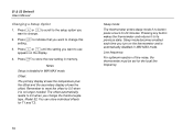
...2. Line frequency: For optimum rejection of line noise, the thermometer must be set for T1 and T2. Press E to its previous state. Model 52: You can store individual offsets for the local line frequency. 10 The offset automatically resets to change this setting. 3. Press E to indicate that .... Press K or N to scroll to the setup option you want to 0.0 when it to store the new setting in memory. 51 & 52 Series II Users Manual Changing a Setup Option 1. Remember to reset the offset to change the thermocouple type. Press K or N until the setting you want to use...
...2. Line frequency: For optimum rejection of line noise, the thermometer must be set for T1 and T2. Press E to its previous state. Model 52: You can store individual offsets for the local line frequency. 10 The offset automatically resets to change this setting. 3. Press E to indicate that .... Press K or N to scroll to the setup option you want to 0.0 when it to store the new setting in memory. 51 & 52 Series II Users Manual Changing a Setup Option 1. Remember to reset the offset to change the thermocouple type. Press K or N until the setting you want to use...
FE 51 & 52 II Users Manual
Page 16
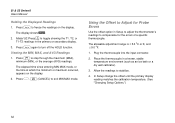
...; 5.0 oC or K, and ± 9.0 oF. 1. Plug the thermocouple into the input connector. 2. Place the thermocouple in Setup to adjust the thermometer's readings to stabilize. 4. Model 52: Press T to step through the maximum (MAX), minimum (MIN), or the average (AVG) readings. Press M to toggle showing the T1, T2, or T1-T2 readings... readings to compensate for Probe Errors Use the offset option in a known, stable temperature environment (such as an ice bath or a dry well calibrator). 3. 51 & 52 Series II Users Manual Holding the Displayed Readings 1.
...; 5.0 oC or K, and ± 9.0 oF. 1. Plug the thermocouple into the input connector. 2. Place the thermocouple in Setup to adjust the thermometer's readings to stabilize. 4. Model 52: Press T to step through the maximum (MAX), minimum (MIN), or the average (AVG) readings. Press M to toggle showing the T1, T2, or T1-T2 readings... readings to compensate for Probe Errors Use the offset option in a known, stable temperature environment (such as an ice bath or a dry well calibrator). 3. 51 & 52 Series II Users Manual Holding the Displayed Readings 1.
FE 51 & 52 II Users Manual
Page 17
... cleaner. Turn off the thermometer if necessary. 2. Wipe with a damp sponge or soft rag. 51 & 52 Series II Maintenance Calibration To ensure that you or follow the calibration procedure in the service manual listed in Table 1 before replacing the batteries. 1. Replace the three AA batteries. 4. Specifications Environmental Operating &#... the battery door and tighten the screw. Loosen the screw and remove the battery door. 3. To calibrate the thermometer, contact Fluke for the Service Center nearest you calibrate the thermometer annually, starting one year after purchase.
... cleaner. Turn off the thermometer if necessary. 2. Wipe with a damp sponge or soft rag. 51 & 52 Series II Maintenance Calibration To ensure that you or follow the calibration procedure in the service manual listed in Table 1 before replacing the batteries. 1. Replace the three AA batteries. 4. Specifications Environmental Operating &#... the battery door and tighten the screw. Loosen the screw and remove the battery door. 3. To calibrate the thermometer, contact Fluke for the Service Center nearest you calibrate the thermometer annually, starting one year after purchase.
FE 51 & 52 II Users Manual
Page 18
... 1.0 oC / oF / K ≥ 1000o 14 Equipment of OVERVOLTAGE CATEGORY I , Pollution Degree 2 per IEC1010-1* * Refers to the level of Impulse Withstand Voltage protection provided. 51 & 52 Series II Users Manual General Weight 280 g (10 oz) Dimensions (without holster) 2.8 cm × 7.8 cm × 16.2 cm (1.1 in × 3 in × 6.4 in) Battery Certification 3 AA batteries P, ) s Safety...
... 1.0 oC / oF / K ≥ 1000o 14 Equipment of OVERVOLTAGE CATEGORY I , Pollution Degree 2 per IEC1010-1* * Refers to the level of Impulse Withstand Voltage protection provided. 51 & 52 Series II Users Manual General Weight 280 g (10 oz) Dimensions (without holster) 2.8 cm × 7.8 cm × 16.2 cm (1.1 in × 3 in × 6.4 in) Battery Certification 3 AA batteries P, ) s Safety...
FE 51 & 52 II Users Manual
Page 19
...& 52 Series II Replacement Parts and Accessories Replacement Parts and Accessories Accessory Part Number Holster and Flex Stand™ Assembly 1272438 AA NEDA 15A IEC LR6 batteries 376756 80PK-1 K-Type Bead Thermocouple 773135 CD-ROM 1276106 Service Manual 1276123 ...N-type; and 0.08 % of reading for J-, K-, E-, and N-type; Electrical (cont.) Measurement Accuracy, T1, T2, or T1-T2 (Model 52) Temperature Coefficient Electromagnetic Compatibility Maximum Differential Common Mode Voltage Temperature Scale J-, K-, T-, reading + 0a.n3doEC-t(y0p.5e:o±F[)0] .05 % of [below ...
...& 52 Series II Replacement Parts and Accessories Replacement Parts and Accessories Accessory Part Number Holster and Flex Stand™ Assembly 1272438 AA NEDA 15A IEC LR6 batteries 376756 80PK-1 K-Type Bead Thermocouple 773135 CD-ROM 1276106 Service Manual 1276123 ...N-type; and 0.08 % of reading for J-, K-, E-, and N-type; Electrical (cont.) Measurement Accuracy, T1, T2, or T1-T2 (Model 52) Temperature Coefficient Electromagnetic Compatibility Maximum Differential Common Mode Voltage Temperature Scale J-, K-, T-, reading + 0a.n3doEC-t(y0p.5e:o±F[)0] .05 % of [below ...

FE 51 & 52 II Users Manual
Page 20
51 & 52 Series II Users Manual 16
51 & 52 Series II Users Manual 16


