
FE 175,177,179 Users Manual
Page 3
...Contacting Fluke ...1 "Warning" and "Caution" Statements 1 Unsafe Voltage...1 Test Lead Alert ...1 Battery Saver ("Sleep Mode 2 Terminals ...2 Rotary Switch Positions...2 Display ...3 MIN MAX AVG Recording Mode 4 Display HOLD and AutoHOLD Modes 4 YELLOW Button ...4 Display Backlight (Model 177 and 179 Only ......6 Testing for Continuity...7 Measuring Temperature (Model 179 Only 7 Testing Diodes ...7 Measuring AC or DC Current 8 Understanding AC Zero Input Behavior of True RMS Meters 8 Measuring Frequency...9 Using the Bar Graph...9 Cleaning ...10 Testing the Fuses...10 Replacing...
...Contacting Fluke ...1 "Warning" and "Caution" Statements 1 Unsafe Voltage...1 Test Lead Alert ...1 Battery Saver ("Sleep Mode 2 Terminals ...2 Rotary Switch Positions...2 Display ...3 MIN MAX AVG Recording Mode 4 Display HOLD and AutoHOLD Modes 4 YELLOW Button ...4 Display Backlight (Model 177 and 179 Only ......6 Testing for Continuity...7 Measuring Temperature (Model 179 Only 7 Testing Diodes ...7 Measuring AC or DC Current 8 Understanding AC Zero Input Behavior of True RMS Meters 8 Measuring Frequency...9 Using the Bar Graph...9 Cleaning ...10 Testing the Fuses...10 Replacing...

FE 175,177,179 Users Manual
Page 5
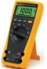
... hazardous conditions and actions that the test leads are in the correct terminals, LEAd is displayed. CAT III meters are designed to make a measurement with a 6000-count, 3 3/4-digit display and a bar graph. The Fluke Model 175, Model 177, and Model 179 are batterypowered, true-RMS multimeters (hereafter "the Meter") with a test lead in an incorrect terminal...
... hazardous conditions and actions that the test leads are in the correct terminals, LEAd is displayed. CAT III meters are designed to make a measurement with a 6000-count, 3 3/4-digit display and a bar graph. The Fluke Model 175, Model 177, and Model 179 are batterypowered, true-RMS multimeters (hereafter "the Meter") with a test lead in an incorrect terminal...

FE 175,177,179 Users Manual
Page 7
... immediately. Have Meter serviced. Display . 5 6 4 3 2 1 7 8 7 9 13 12 11 14 10 15 No. 1 2 OSymbol s h3 K 4 Y 5 6 Amh MAX , MIN, AVG AIK02F.EPS Meaning Continuity test. Replace battery. 10 610000mV All possible ranges. 11 Bar graph Analog display. 12 Auto Range The Meter... selects the range with the best resolution. Display freezes present reading. In MIN MAX AVG mode, MIN MAX AVG recording is moved to or...
... immediately. Have Meter serviced. Display . 5 6 4 3 2 1 7 8 7 9 13 12 11 14 10 15 No. 1 2 OSymbol s h3 K 4 Y 5 6 Amh MAX , MIN, AVG AIK02F.EPS Meaning Continuity test. Replace battery. 10 610000mV All possible ranges. 11 Bar graph Analog display. 12 Auto Range The Meter... selects the range with the best resolution. Display freezes present reading. In MIN MAX AVG mode, MIN MAX AVG recording is moved to or...

FE 175,177,179 Users Manual
Page 13
... scale. The trigger level is useful for making peak and null adjustments and for all ranges. Because the bar graph updates about 40 times per second, which is 10 times faster than the digital display, the bar graph is 0 V, 0 A AC for observing rapidly changing inputs. An input of −30 V lights the negative sign and...
... scale. The trigger level is useful for making peak and null adjustments and for all ranges. Because the bar graph updates about 40 times per second, which is 10 times faster than the digital display, the bar graph is 0 V, 0 A AC for observing rapidly changing inputs. An input of −30 V lights the negative sign and...

FE 175,177,179 Users Manual
Page 15
... counts Altitude: Operating: 2000 m; Specifications Specifications Accuracy is specified for A input: 8 kV peak per IEC 61010 440 mA, 1000 V FAST Fuse 11 A, 1000 V FAST Fuse Display: Digital: 6000 counts, updates 4/sec Bar Graph: 33 segments;
... counts Altitude: Operating: 2000 m; Specifications Specifications Accuracy is specified for A input: 8 kV peak per IEC 61010 440 mA, 1000 V FAST Fuse 11 A, 1000 V FAST Fuse Display: Digital: 6000 counts, updates 4/sec Bar Graph: 33 segments;


