
FE 1587-1577 Users Manual
Page 1
Printed in USA All product names are trademarks of their respective companies. ® 1587/1577 Insulation Multimeters Users Manual All rights reserved. PN 2401027 April 2005 Rev.1, 1/06 © 2005-2006 Fluke Corporation.
Printed in USA All product names are trademarks of their respective companies. ® 1587/1577 Insulation Multimeters Users Manual All rights reserved. PN 2401027 April 2005 Rev.1, 1/06 © 2005-2006 Fluke Corporation.

FE 1587-1577 Users Manual
Page 3
Table of Contents Title Page Introduction ...1 Contacting Fluke ...1 Safety Information ...2 Accessories ...4 Unsafe Voltage...4 Test Lead Alert ...4 Battery Saver (Sleep Mode 4 Rotary Switch Positions 5 Buttons ...6 Understanding the Display 8 Input Terminals...11 Power-Up Options ...12 AutoHold Mode...13 MIN MAX AVG Recording Mode 13 Manual Ranging and Autoranging 14 Understanding AC Zero Input Behavior of True RMS Meters 15 Low-Pass Filter (Model 1587 and 1587T 15 i
Table of Contents Title Page Introduction ...1 Contacting Fluke ...1 Safety Information ...2 Accessories ...4 Unsafe Voltage...4 Test Lead Alert ...4 Battery Saver (Sleep Mode 4 Rotary Switch Positions 5 Buttons ...6 Understanding the Display 8 Input Terminals...11 Power-Up Options ...12 AutoHold Mode...13 MIN MAX AVG Recording Mode 13 Manual Ranging and Autoranging 14 Understanding AC Zero Input Behavior of True RMS Meters 15 Low-Pass Filter (Model 1587 and 1587T 15 i

FE 1587-1577 Users Manual
Page 4
1587/1577 Users Manual Making Basic Measurements 16 Measuring AC and DC Voltage 17 Measuring Temperature (Model 1587 and 1587T 18 Measuring Resistance 19 Measuring Capacitance (Model 1587 and ... Specifications...29 General Specifications 29 Electrical Specifications 30 AC Voltage Measurement 30 1587 and 1587T Accuracy 30 1587 and 1587T Low-Pass Filter Voltage 31 1577 Accuracy...31 DC Voltage Measurement 32 DC Millivolts Measurement 32 DC and AC Current Measurement 33 Ohms Measurement 34 Diode Test (1587 and 1587T Only...
1587/1577 Users Manual Making Basic Measurements 16 Measuring AC and DC Voltage 17 Measuring Temperature (Model 1587 and 1587T 18 Measuring Resistance 19 Measuring Capacitance (Model 1587 and ... Specifications...29 General Specifications 29 Electrical Specifications 30 AC Voltage Measurement 30 1587 and 1587T Accuracy 30 1587 and 1587T Low-Pass Filter Voltage 31 1577 Accuracy...31 DC Voltage Measurement 32 DC Millivolts Measurement 32 DC and AC Current Measurement 33 Ohms Measurement 34 Diode Test (1587 and 1587T Only...

FE 1587-1577 Users Manual
Page 6
1587/1577 Users Manual iv
1587/1577 Users Manual iv

FE 1587-1577 Users Manual
Page 8
1587/1577 Users Manual vi
1587/1577 Users Manual vi

FE 1587-1577 Users Manual
Page 10
1587/1577 Users Manual viii
1587/1577 Users Manual viii
FE 1587-1577 Users Manual
Page 11
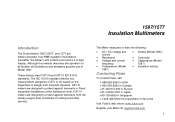
...manual describes the operation of all models, all illustrations and examples assume use of danger from transient impulses. CAT IV meters are designed to IV) based on the magnitude of Model 1587. The IEC 61010 standard defines four measurement categories (CAT I to protect against transients in the world Visit Fluke...'s web site at: www.fluke.com Register your Meter at the distribution level; 1587/1577 Insulation Multimeters Introduction The Fluke Models 1587,1587T, and 1577 are designed to protect against transients from ...
...manual describes the operation of all models, all illustrations and examples assume use of danger from transient impulses. CAT IV meters are designed to IV) based on the magnitude of Model 1587. The IEC 61010 standard defines four measurement categories (CAT I to protect against transients in the world Visit Fluke...'s web site at: www.fluke.com Register your Meter at the distribution level; 1587/1577 Insulation Multimeters Introduction The Fluke Models 1587,1587T, and 1577 are designed to protect against transients from ...
FE 1587-1577 Users Manual
Page 12
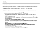
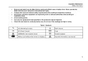
1587/1577 Users Manual Safety Information Use the Meter only as specified in this manual. A XWWarning identifies hazardous conditions and actions that could cause bodily harm or death. These voltages pose a shock hazard. • Replace the battery as soon as ... data. See Table 1 for measurements before connecting Meter to circuit under test, or cause permanent loss of symbols used on the Meter and in this manual or the protection provided by measuring a known voltage. • Do not apply more than the rated voltage as the low battery indicator (b) appears. • ...
1587/1577 Users Manual Safety Information Use the Meter only as specified in this manual. A XWWarning identifies hazardous conditions and actions that could cause bodily harm or death. These voltages pose a shock hazard. • Replace the battery as soon as ... data. See Table 1 for measurements before connecting Meter to circuit under test, or cause permanent loss of symbols used on the Meter and in this manual or the protection provided by measuring a known voltage. • Do not apply more than the rated voltage as the low battery indicator (b) appears. • ...
FE 1587-1577 Users Manual
Page 13
... fuse specified or the protection may be impaired. • Check the test leads for continuity before opening the Meter case or battery door. B F X b Table 1. see manual 3 Battery (Low battery when shown on display.) J I T W Earth Ground Fuse Double Insulated Important information; Do not use .
... fuse specified or the protection may be impaired. • Check the test leads for continuity before opening the Meter case or battery door. B F X b Table 1. see manual 3 Battery (Low battery when shown on display.) J I T W Earth Ground Fuse Double Insulated Important information; Do not use .

FE 1587-1577 Users Manual
Page 14
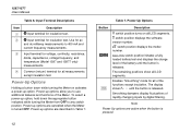
... a potentially hazardous voltage, when the Meter detects a voltage ≥ 30 V or a voltage overload (OL), the Z symbol is displayed. 1587/1577 Users Manual Accessories Model Leads Probes Clips 1587 and 1587T TL224 TP74 AC285 1577 TL224 TL74 AC285 Unsafe Voltage To alert you move the rotary switch to the presence of Sleep mode when...
... a potentially hazardous voltage, when the Meter detects a voltage ≥ 30 V or a voltage overload (OL), the Z symbol is displayed. 1587/1577 Users Manual Accessories Model Leads Probes Clips 1587 and 1587T TL224 TP74 AC285 1577 TL224 TL74 AC285 Unsafe Voltage To alert you move the rotary switch to the presence of Sleep mode when...

FE 1587-1577 Users Manual
Page 16
...button to 400 mA (600 mA overload for 2 minutes maximum). Buttons Use the buttons to 400 mA (600 mA overload for 2 minutes maximum). 1587/1577 Users Manual Table 2. Ohms from 3.00 mA to activate features that augment the function selected with 50, 100, 250, 500 (default), and 1000 V source on... the 1587 or 500 (default) and 1000 V source on the 1577 or 50 V (default) and 100 V on at 100 Ω. Performs insulation test with the rotary...
...button to 400 mA (600 mA overload for 2 minutes maximum). Buttons Use the buttons to 400 mA (600 mA overload for 2 minutes maximum). 1587/1577 Users Manual Table 2. Ohms from 3.00 mA to activate features that augment the function selected with 50, 100, 250, 500 (default), and 1000 V source on... the 1587 or 500 (default) and 1000 V source on the 1577 or 50 V (default) and 100 V on at 100 Ω. Performs insulation test with the rotary...
FE 1587-1577 Users Manual
Page 17
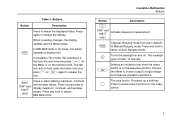
... 1587T only) Activate frequency measurement. r Changes Ranging mode from Auto (default) to start retaining maximum, minimum, and average values. m (1587 and 1587T only) Press to Manual Ranging mode. Buttons Button Description Press to release the display. h In MIN MAX AVG or Hz mode, this schedules a test lock the next time you...
... 1587T only) Activate frequency measurement. r Changes Ranging mode from Auto (default) to start retaining maximum, minimum, and average values. m (1587 and 1587T only) Press to Manual Ranging mode. Buttons Button Description Press to release the display. h In MIN MAX AVG or Hz mode, this schedules a test lock the next time you...

FE 1587-1577 Users Manual
Page 18
... 5. Error messages that may appear on the remote probe. L LOCK Indicates a test lock will be applied the next time you press h or t again. - 1587/1577 Users Manual Understanding the Display Display indicators are described in Table 4. Display Indicators bav01f.eps 8 Table 4. Display Indicators Indicator Description b Low battery. Minus, or greater than symbols...
... 5. Error messages that may appear on the remote probe. L LOCK Indicates a test lock will be applied the next time you press h or t again. - 1587/1577 Users Manual Understanding the Display Display indicators are described in Table 4. Display Indicators bav01f.eps 8 Table 4. Display Indicators Indicator Description b Low battery. Minus, or greater than symbols...

FE 1587-1577 Users Manual
Page 20
...for insulation test: 50, 100, 250, 500 (default) or 1000 V on the 1587. 500 (default) and 1000 V ranges available on the 1577. 50 (default) and 100 V on the primary display and indicates that the battery is replaced. The b also appears when batt is on the ...to perform an insulation test. Appears on the primary display. This message disappears when the rotary switch is present. 10 Table 5. 1587/1577 Users Manual Table 4. Error Messages Message Description batt bat OPEn LEAd 15--Err Appears on the 1587T. Model detect error. Display Indicators (cont.) Feature...
...for insulation test: 50, 100, 250, 500 (default) or 1000 V on the 1587. 500 (default) and 1000 V ranges available on the 1577. 50 (default) and 100 V on the primary display and indicates that the battery is replaced. The b also appears when batt is on the ...to perform an insulation test. Appears on the primary display. This message disappears when the rotary switch is present. 10 Table 5. 1587/1577 Users Manual Table 4. Error Messages Message Description batt bat OPEn LEAd 15--Err Appears on the 1587T. Model detect error. Display Indicators (cont.) Feature...
FE 1587-1577 Users Manual
Page 22
... Options Holding a button down the appropriate button indicated while turning the Meter from OFF to 400 mA and current frequency measurements. The display shows S - - - 1587/1577 Users Manual . Use for voltage, continuity, resistance, diode, capacitance, voltage frequency, and temperature (Model 1587 and 1587T only) measurements. C Input terminal for ac and dc milliamp...
... Options Holding a button down the appropriate button indicated while turning the Meter from OFF to 400 mA and current frequency measurements. The display shows S - - - 1587/1577 Users Manual . Use for voltage, continuity, resistance, diode, capacitance, voltage frequency, and temperature (Model 1587 and 1587T only) measurements. C Input terminal for ac and dc milliamp...
FE 1587-1577 Users Manual
Page 24
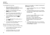
...the rotary switch. S turns off. • To exit and erase stored readings, press m for one second or turn the rotary switch. Note You cannot manually change . 3. The Meter returns to step through the high (MAX), low (MIN), average (AVG), and present readings. • To pause MIN MAX ...AVG recording without erasing stored values, press h. 1587/1577 Users Manual To use MIN MAX AVG recording: • Make sure the Meter is in the desired measurement function and range. (Autoranging is disabled in the MIN...
...the rotary switch. S turns off. • To exit and erase stored readings, press m for one second or turn the rotary switch. Note You cannot manually change . 3. The Meter returns to step through the high (MAX), low (MIN), average (AVG), and present readings. • To pause MIN MAX ...AVG recording without erasing stored values, press h. 1587/1577 Users Manual To use MIN MAX AVG recording: • Make sure the Meter is in the desired measurement function and range. (Autoranging is disabled in the MIN...
FE 1587-1577 Users Manual
Page 25
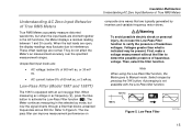
... the Low-Pass filter function, the Meter goes to interference. Low-Pass Filter (Model 1587 and 1587T) The 1587 is indicated may fluctuate due to Manual mode. Understanding AC Zero Input Behavior of True RMS Meters True RMS Meters accurately measure distorted waveforms, but now the signal diverts through a filter that...
... the Low-Pass filter function, the Meter goes to interference. Low-Pass Filter (Model 1587 and 1587T) The 1587 is indicated may fluctuate due to Manual mode. Understanding AC Zero Input Behavior of True RMS Meters True RMS Meters accurately measure distorted waveforms, but now the signal diverts through a filter that...

FE 1587-1577 Users Manual
Page 26
...live lead; This procedure improves the accuracy of an ac voltage, measure the ac voltage first. Note the ac voltage range, then manually select a dc voltage range equal to the Meter, disconnect circuit power and discharge all high-voltage capacitors before removing the common test lead. ...1587/1577 Users Manual Making Basic Measurements The figures on the following pages show how to the circuit or device, connect the common (COM) test lead ...
...live lead; This procedure improves the accuracy of an ac voltage, measure the ac voltage first. Note the ac voltage range, then manually select a dc voltage range equal to the Meter, disconnect circuit power and discharge all high-voltage capacitors before removing the common test lead. ...1587/1577 Users Manual Making Basic Measurements The figures on the following pages show how to the circuit or device, connect the common (COM) test lead ...

FE 1587-1577 Users Manual
Page 28
... for 260 °C (500 °F). For temperatures out of a type-K thermocouple (included). Choose between degrees Celsius (°C) or degrees Fahrenheit (°F) by pressing r. 1587/1577 Users Manual Measuring Temperature (Model 1587 and 1587T) The Meter measures the temperature of that while the Meter is rated for -40 °C to 537 °C ( -40...
... for 260 °C (500 °F). For temperatures out of a type-K thermocouple (included). Choose between degrees Celsius (°C) or degrees Fahrenheit (°F) by pressing r. 1587/1577 Users Manual Measuring Temperature (Model 1587 and 1587T) The Meter measures the temperature of that while the Meter is rated for -40 °C to 537 °C ( -40...

FE 1587-1577 Users Manual
Page 30
The beeper sounds when a short ( The beeper allows you to perform quick continuity tests without having to watch the display. To test for Continuity The continuity test features a beeper that sounds as long as shown in Figure 10. 1587/1577 Users Manual Testing for continuity, set up the Meter as a circuit is complete.
The beeper sounds when a short ( The beeper allows you to perform quick continuity tests without having to watch the display. To test for Continuity The continuity test features a beeper that sounds as long as shown in Figure 10. 1587/1577 Users Manual Testing for continuity, set up the Meter as a circuit is complete.


