Fluke 1550B MegOhmMeter Datasheet
Page 1
... user that user can be used for a wide range of 250 V, 500 V, 1000 V, 2500 V and 5000 V • Additional test voltages available in the custom carrying case, for a rugged field testing kit. • Standard test voltages of tests: from 1000 to 5000 volts • Measures up to a Windows® PC • Custom soft case for tester and accessories...
... user that user can be used for a wide range of 250 V, 500 V, 1000 V, 2500 V and 5000 V • Additional test voltages available in the custom carrying case, for a rugged field testing kit. • Standard test voltages of tests: from 1000 to 5000 volts • Measures up to a Windows® PC • Custom soft case for tester and accessories...
Fluke 1550B MegOhmMeter Datasheet
Page 2
..., 2000, NT4.0 Two-year warranty Included accessories Test leads and low leakage probes Alligator clips Interface adapter and cable Quicklink 1550B PC software Line cord Soft carrying case with waterproof bottom User's manual CD with battery) 170 mm x 242 mm x 330 mm (6.7 in x 9.5 in x 13.0 in) 4 kg (8.8 lbs) Power Battery type 12 volt, lead-acid, rechargeable Charger input (AC) 85 to 50 °...
..., 2000, NT4.0 Two-year warranty Included accessories Test leads and low leakage probes Alligator clips Interface adapter and cable Quicklink 1550B PC software Line cord Soft carrying case with waterproof bottom User's manual CD with battery) 170 mm x 242 mm x 330 mm (6.7 in x 9.5 in x 13.0 in) 4 kg (8.8 lbs) Power Battery type 12 volt, lead-acid, rechargeable Charger input (AC) 85 to 50 °...
FE 1550B Users Manual
Page 2
... specifications for 90 days. If Fluke determines that service center, with a description of repair/replacement parts when product purchased in one country is returned to any provision of this Warranty is held invalid or unenforceable by use and service. Fluke's warranty obligation is limited, at : www.fluke.com 11/99 Box 9090 Everett, WA 98206-9090 U.S.A. Fluke warrants that software will be error free...
... specifications for 90 days. If Fluke determines that service center, with a description of repair/replacement parts when product purchased in one country is returned to any provision of this Warranty is held invalid or unenforceable by use and service. Fluke's warranty obligation is limited, at : www.fluke.com 11/99 Box 9090 Everett, WA 98206-9090 U.S.A. Fluke warrants that software will be error free...
FE 1550B Users Manual
Page 3
... Title Page Introduction 1 Contacting Fluke 1 Unpacking the Meter 2 Safety Information 3 Symbols 4 Operating the Meter 4 Turning the Meter On and Off 4 Using the Pushbuttons 5 Understanding the Display 6 Charging the Battery 6 Using the Guard Terminal 8 Making Measurements 10 Connecting to the Circuit Under Test 10 Selecting a Pre-set Test Voltage 11 Programming a Test Voltage 12 Selecting a Ramp or Steady-State Test 13 Setting a Timed Test 13 Polarization Index...
... Title Page Introduction 1 Contacting Fluke 1 Unpacking the Meter 2 Safety Information 3 Symbols 4 Operating the Meter 4 Turning the Meter On and Off 4 Using the Pushbuttons 5 Understanding the Display 6 Charging the Battery 6 Using the Guard Terminal 8 Making Measurements 10 Connecting to the Circuit Under Test 10 Selecting a Pre-set Test Voltage 11 Programming a Test Voltage 12 Selecting a Ramp or Steady-State Test 13 Setting a Timed Test 13 Polarization Index...

FE 1550B Users Manual
Page 5
List of Replacable Parts 21 3. 1550B Accessories 21 List of Tables Table Title Page 1. Connecting to the Circuit Under Test 10 9. Power Supply Connections 7 5. Surface Leakage Current 8 6. Display Features 6 4. IR Port on 1550B MegOhmMeter 18 iii Symbols 4 2. Guard Terminal Connection 9 7. Improved Guard Terminal Connection 9 8. Standard Items Provided 2 2. Pushbuttons 5 3. List of Figures Figure Title Page 1.
List of Replacable Parts 21 3. 1550B Accessories 21 List of Tables Table Title Page 1. Connecting to the Circuit Under Test 10 9. Power Supply Connections 7 5. Surface Leakage Current 8 6. Display Features 6 4. IR Port on 1550B MegOhmMeter 18 iii Symbols 4 2. Guard Terminal Connection 9 7. Improved Guard Terminal Connection 9 8. Standard Items Provided 2 2. Pushbuttons 5 3. List of Figures Figure Title Page 1.
FE 1550B Users Manual
Page 7
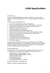
... Fluke To contact Fluke for product information, operating assistance, service, or to 1 TΩ ⇒ Polarization Index (PI) measurement ⇒ Dielectric Absorption Ratio (DAR) measurement ⇒ Ramp mode that linearly increases (100 V/s) the applied test voltage ⇒ Test timer and storage for test results with user settable ID tag ⇒ Breakdown voltage indication ⇒ Rechargeable lead-acid battery ⇒ Auto shutoff...
... Fluke To contact Fluke for product information, operating assistance, service, or to 1 TΩ ⇒ Polarization Index (PI) measurement ⇒ Dielectric Absorption Ratio (DAR) measurement ⇒ Ramp mode that linearly increases (100 V/s) the applied test voltage ⇒ Test timer and storage for test results with user settable ID tag ⇒ Breakdown voltage indication ⇒ Rechargeable lead-acid battery ⇒ Auto shutoff...
FE 1550B Users Manual
Page 8
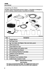
... the place of purchase immediately. 1 2 3 5 7 4 6 8 11 12 9 10 ASW01F.EPS Item Description A English Manual B AC Power Cord C X Test Cables with Alligator Clips (red, black, green) D Soft Carrying Case E Quick Reference Card F Infrared Adapter with the items shown in Figure 1. 1550B Users Manual Unpacking the Meter The Meter comes with interface cable G CD containing Users Manual H CD containing FlukeView Forms Basic I Software License Agreement J Registration Card K FlukeView Forms Installation Guide L USB-IR Cable Installation Guide Figure 1.
... the place of purchase immediately. 1 2 3 5 7 4 6 8 11 12 9 10 ASW01F.EPS Item Description A English Manual B AC Power Cord C X Test Cables with Alligator Clips (red, black, green) D Soft Carrying Case E Quick Reference Card F Infrared Adapter with the items shown in Figure 1. 1550B Users Manual Unpacking the Meter The Meter comes with interface cable G CD containing Users Manual H CD containing FlukeView Forms Basic I Software License Agreement J Registration Card K FlukeView Forms Installation Guide L USB-IR Cable Installation Guide Figure 1.
FE 1550B Users Manual
Page 9
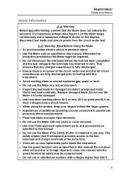
... ensures that any parts or cover removed. • Use only Fluke approved replacement parts, and accessories as specified in this manual. • Do not use the Meter if it looks damaged. • Use care when working alone or around explosive gas, vapor or dust. • Do not use in distribution systems with voltages higher than 660 V. 3 MegOhmMeter Safety Information Safety Information XW Warning Before...
... ensures that any parts or cover removed. • Use only Fluke approved replacement parts, and accessories as specified in this manual. • Do not use the Meter if it looks damaged. • Use care when working alone or around explosive gas, vapor or dust. • Do not use in distribution systems with voltages higher than 660 V. 3 MegOhmMeter Safety Information Safety Information XW Warning Before...
FE 1550B Users Manual
Page 10
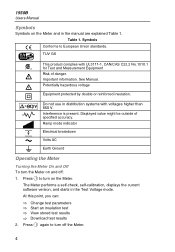
... standards. Important information. Ramp mode indicator b Electrical breakdown B Volts AC J Earth Ground Operating the Meter Turning the Meter On and Off To turn off : 1. See Manual. Table 1. The Meter performs a self-check, self-calibration, displays the current software version, and starts in distribution systems with UL3111-1, CAN/CAS C22.2 No.1010.1 for Test and Measurement Equipment Risk of specified accuracy. 1550B Users Manual Symbols Symbols on...
... standards. Important information. Ramp mode indicator b Electrical breakdown B Volts AC J Earth Ground Operating the Meter Turning the Meter On and Off To turn off : 1. See Manual. Table 1. The Meter performs a self-check, self-calibration, displays the current software version, and starts in distribution systems with UL3111-1, CAN/CAS C22.2 No.1010.1 for Test and Measurement Equipment Risk of specified accuracy. 1550B Users Manual Symbols Symbols on...

FE 1550B Users Manual
Page 11
... ENTER TEST Item A B C D E F G 1 2 3 4 5 6 7 ASW02F.EPS Button Description O Turns the Meter off and on. Enter button. Push and hold the button for viewing, and scroll through test voltages, stored test results, timer duration, and memory locations. MegOhmMeter Operating the Meter Using the Pushbuttons Use the pushbuttons (Figure 2) to control operation of the Meter, select test results for 1 second to start a test. ON/ OFF FUNCTION (yes) UP...
... ENTER TEST Item A B C D E F G 1 2 3 4 5 6 7 ASW02F.EPS Button Description O Turns the Meter off and on. Enter button. Push and hold the button for viewing, and scroll through test voltages, stored test results, timer duration, and memory locations. MegOhmMeter Operating the Meter Using the Pushbuttons Use the pushbuttons (Figure 2) to control operation of the Meter, select test results for 1 second to start a test. ON/ OFF FUNCTION (yes) UP...
FE 1550B Users Manual
Page 12
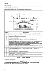
... voltage selection (250 V, 500 V, 1000 V, 2500 V, or 5000 V) Battery charge status. Potentially hazardous voltage is present at the test terminals. Indicates voltage, test current, capacitance, programmable test voltages, and menu options. Figure 3. 1550B Users Manual Understanding the Display Display annunciators are shown and described in Ramp mode. Electrical breakdown in Figure 3. 34 5 2 V 5000V 2500V 000V 500V 250V 6 1 0M...
... voltage selection (250 V, 500 V, 1000 V, 2500 V, or 5000 V) Battery charge status. Potentially hazardous voltage is present at the test terminals. Indicates voltage, test current, capacitance, programmable test voltages, and menu options. Figure 3. 1550B Users Manual Understanding the Display Display annunciators are shown and described in Ramp mode. Electrical breakdown in Figure 3. 34 5 2 V 5000V 2500V 000V 500V 250V 6 1 0M...
FE 1550B Users Manual
Page 13
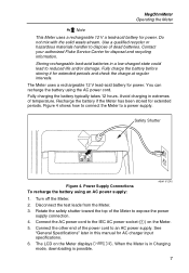
... Fluke Service Center for AC charger input specifications. 6. You can recharge the battery using an AC power supply: ASW11F.EPS 1. Connect the AC power cord to dispose of the Meter to a power supply. See "General Specifications" later in extremes of the power cord to reduced life and/or damage. MegOhmMeter Operating the Meter = Pb Note This Meter uses a rechargeable 12 V a lead-acid battery for extended periods and check the charge at regular intervals. Power Supply Connections...
... Fluke Service Center for AC charger input specifications. 6. You can recharge the battery using an AC power supply: ASW11F.EPS 1. Connect the AC power cord to dispose of the Meter to a power supply. See "General Specifications" later in extremes of the power cord to reduced life and/or damage. MegOhmMeter Operating the Meter = Pb Note This Meter uses a rechargeable 12 V a lead-acid battery for extended periods and check the charge at regular intervals. Power Supply Connections...

FE 1550B Users Manual
Page 15
....EPS 9 Shield ( ) Optional (G) ( ) Leakage Current Figure 6. MegOhmMeter Operating the Meter Figure 6 shows how to prevent surface current leakage by connecting the Guard terminal to the unused wire and coupling it to the inner insulation. Guard Terminal Connection ASW14F.EPS Figure 7 shows how to improve the measurement setup by connecting a lead from the measurement path between conductors. This...
....EPS 9 Shield ( ) Optional (G) ( ) Leakage Current Figure 6. MegOhmMeter Operating the Meter Figure 6 shows how to prevent surface current leakage by connecting the Guard terminal to the unused wire and coupling it to the inner insulation. Guard Terminal Connection ASW14F.EPS Figure 7 shows how to improve the measurement setup by connecting a lead from the measurement path between conductors. This...
FE 1550B Users Manual
Page 18
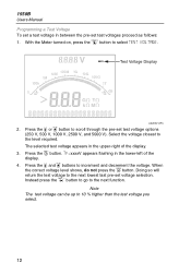
...buttons to the level required. With the Meter turned on, press the H button to the next lowest last pre-set voltage selection. The selected test voltage appears in the upper-right of the display. 4. V 500V 0M 00M G 0G M 00G 00k T 0 GT kM Test Voltage Display ASW05F.EPS 2. 1550B Users Manual Programming a Test Voltage To set... correct voltage level shows, do not press the e button. TV=xxxxV appears flashing in the lower-left of the display. 3. Instead press the H button to go to scroll through the pre-set test voltages proceed as follows: 1. Note The test voltage...
...buttons to the level required. With the Meter turned on, press the H button to the next lowest last pre-set voltage selection. The selected test voltage appears in the upper-right of the display. 4. V 500V 0M 00M G 0G M 00G 00k T 0 GT kM Test Voltage Display ASW05F.EPS 2. 1550B Users Manual Programming a Test Voltage To set... correct voltage level shows, do not press the e button. TV=xxxxV appears flashing in the lower-left of the display. 3. Instead press the H button to go to scroll through the pre-set test voltages proceed as follows: 1. Note The test voltage...
FE 1550B Users Manual
Page 20
... the DAR test is measured and stored as invalid data for display during a test by pressing the R button or by DAR=. The results are available for display during a test by pressing the R button or by any tests. • First connect the test leads to the Meter inputs before you make connection to the circuit under 10 minutes. The field...
... the DAR test is measured and stored as invalid data for display during a test by pressing the R button or by DAR=. The results are available for display during a test by pressing the R button or by any tests. • First connect the test leads to the Meter inputs before you make connection to the circuit under 10 minutes. The field...
FE 1550B Users Manual
Page 21
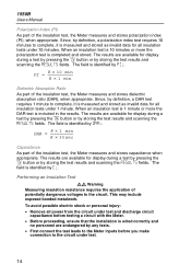
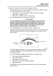
... flashes on the display indicating potentially hazardous voltages may be present on the test terminals. Press the T button for 1 second to 5000 V (50 V/100 V steps) • Ramp Test - If the Meter beeps continuously and a hazardous voltage is shown on , set the available measurement options to test. The Meter beeps 3 times as a trend. Set range: 250V to start the insulation test. Digital...
... flashes on the display indicating potentially hazardous voltages may be present on the test terminals. Press the T button for 1 second to 5000 V (50 V/100 V steps) • Ramp Test - If the Meter beeps continuously and a hazardous voltage is shown on , set the available measurement options to test. The Meter beeps 3 times as a trend. Set range: 250V to start the insulation test. Digital...
FE 1550B Users Manual
Page 24
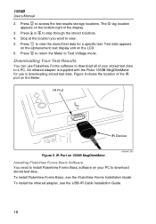
... mode. To install FlukeView Forms Basic, see the USB-IR Cable Installation Guide. 18 To install the infrared adapter, see the FlukeView Forms Installation Guide. Press e to return the Meter to view the stored test data for use FlukeView Forms software to download all of the display. 3. An infrared adapter is supplied with the Fluke 1550B MegOhmMeter for a specific test. Figure 9 shows the location of the IR port on the LCD. 6. IR Port IR PORT...
... mode. To install FlukeView Forms Basic, see the USB-IR Cable Installation Guide. 18 To install the infrared adapter, see the FlukeView Forms Installation Guide. Press e to return the Meter to view the stored test data for use FlukeView Forms software to download all of the display. 3. An infrared adapter is supplied with the Fluke 1550B MegOhmMeter for a specific test. Figure 9 shows the location of the IR port on the LCD. 6. IR Port IR PORT...

FE 1550B Users Manual
Page 25
... change the COM port setting to the virtual COM port used , software drivers must be installed on . 7. See the FlukeView Forms Users Manual file for more information. MegOhmMeter Downloading Your Test Results Downloading Results to PC Note Before the USB-IR cable can be deleted from the 1550B to the PC found in the Meter can be used by the USB-IR cable. 6. With the Meter turned on the Fluke 1550B. See the USB-IR Installation Guide...
... change the COM port setting to the virtual COM port used , software drivers must be installed on . 7. See the FlukeView Forms Users Manual file for more information. MegOhmMeter Downloading Your Test Results Downloading Results to PC Note Before the USB-IR cable can be deleted from the 1550B to the PC found in the Meter can be used by the USB-IR cable. 6. With the Meter turned on the Fluke 1550B. See the USB-IR Installation Guide...
FE 1550B Users Manual
Page 27
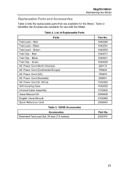
...) AC Power Cord (Continental Europe) AC Power Cord (UK) AC Power Cord (Australia) AC Power Cord (S. Table 3 Identifies the Accessories available for the Meter. Table 2. Red Test Lead - Black Test Clip - Black Test Lead - MegOhmMeter Maintaining the Meter Replaceable Parts and Accessories Table 2 lists the replaceable parts that are available for use with the Meter. Africa) Soft Carrying Case Infrared Cable Assembly Users Manual CD English Users Manual Quick Reference Card Table 3. 1550B Accessories Accessories Extended Test Lead Set, 25 feet (7.6 meters) Part No. 1642584...
...) AC Power Cord (Continental Europe) AC Power Cord (UK) AC Power Cord (Australia) AC Power Cord (S. Table 3 Identifies the Accessories available for the Meter. Table 2. Red Test Lead - Black Test Clip - Black Test Lead - MegOhmMeter Maintaining the Meter Replaceable Parts and Accessories Table 2 lists the replaceable parts that are available for use with the Meter. Africa) Soft Carrying Case Infrared Cable Assembly Users Manual CD English Users Manual Quick Reference Card Table 3. 1550B Accessories Accessories Extended Test Lead Set, 25 feet (7.6 meters) Part No. 1642584...
FE 1550B Users Manual
Page 28
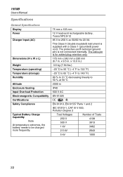
... 22 1550B Users Manual Specifications General Specifications Display Power Charger Input (AC) Dimensions (H x W x L) Weight Temperature (operating) Temperature (storage) Humidity Altitude Enclosure Sealing Input Overload Protection Electromagnetic Compatibility Certifications Safety Compliance Typical Battery Charge Capability Note At temperature extremes, the battery needs to 250 V ac 50/60 Hz 20 VA This Class II (double insulated) instrument is supplied with a Class 1 (grounded) power cord. x 13.0 in . The extra pin is not connected...
... 22 1550B Users Manual Specifications General Specifications Display Power Charger Input (AC) Dimensions (H x W x L) Weight Temperature (operating) Temperature (storage) Humidity Altitude Enclosure Sealing Input Overload Protection Electromagnetic Compatibility Certifications Safety Compliance Typical Battery Charge Capability Note At temperature extremes, the battery needs to 250 V ac 50/60 Hz 20 VA This Class II (double insulated) instrument is supplied with a Class 1 (grounded) power cord. x 13.0 in . The extra pin is not connected...


