

Fluke ScopeMeter Product Datasheet
Page 2
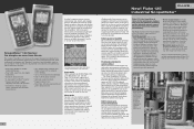
.... On-screen color labels, measurements and warnings are clearly linked to specific waveforms. See dynamic signal behavior instantaneously The Digital Persistence mode (Fluke 190C) helps to 2.5 GS/s real-time sampling per input record length using FlukeView® ScopeMeter software. With up to 22 days ...1000 V independently floating isolated inputs for 1000 V CAT II and 600 V CAT III safety certification • Four hours rechargeable NiMH battery pack See an on bursts of vibration, signal interference or crosstalk. like on both the 190B and 190C Series has been enlarged to...
.... On-screen color labels, measurements and warnings are clearly linked to specific waveforms. See dynamic signal behavior instantaneously The Digital Persistence mode (Fluke 190C) helps to 2.5 GS/s real-time sampling per input record length using FlukeView® ScopeMeter software. With up to 22 days ...1000 V independently floating isolated inputs for 1000 V CAT II and 600 V CAT III safety certification • Four hours rechargeable NiMH battery pack See an on bursts of vibration, signal interference or crosstalk. like on both the 190B and 190C Series has been enlarged to...
Fluke ScopeMeter Product Datasheet
Page 4
...common time related measurements like variable frequency motor drives. Battery powered mobility Up to seven hours battery operation • 600 V CAT III safety certified • Optically isolated interface • Rugged compact case • New Fluke 125 gives bus health and power measurements Dual-input measurement ...to focus on the job at http:// us.fluke.com/usen/products/Fluke+120. The Fluke 125 has all the information on the test tool in one -two-three! It helps you from mains outlets for true on battery life.) Floating measurements, safety certified While conventional ...
...common time related measurements like variable frequency motor drives. Battery powered mobility Up to seven hours battery operation • 600 V CAT III safety certified • Optically isolated interface • Rugged compact case • New Fluke 125 gives bus health and power measurements Dual-input measurement ...to focus on the job at http:// us.fluke.com/usen/products/Fluke+120. The Fluke 125 has all the information on the test tool in one -two-three! It helps you from mains outlets for true on battery life.) Floating measurements, safety certified While conventional ...
Fluke ScopeMeter Product Datasheet
Page 5
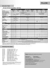
... Save set-ups and screens True-rms multimeter Safety, Power and Warranty Safety (EN61010-1) Battery Line power PC and printer interface Warranty 190C ScopeMeter Series 190B ScopeMeter Series 120 Series Fluke 199C Fluke 196C Fluke 199B Fluke 196B Fluke 192B Fluke 125 Fluke 124 Fluke 123 200 MHz 100 MHz 200 MHz 100 MHz 60 MHz 40 MHz 40 MHz...
... Save set-ups and screens True-rms multimeter Safety, Power and Warranty Safety (EN61010-1) Battery Line power PC and printer interface Warranty 190C ScopeMeter Series 190B ScopeMeter Series 120 Series Fluke 199C Fluke 196C Fluke 199B Fluke 196B Fluke 192B Fluke 125 Fluke 124 Fluke 123 200 MHz 100 MHz 200 MHz 100 MHz 60 MHz 40 MHz 40 MHz...

Fluke 123, 124, and 125 Scopemeter Datasheet
Page 1
... one affordable, easy-to-use instrument. It's a truly integrated test tool, with 0.01 Ohm resolution (Fluke 125) v Cursors (Fluke 124, 125) v Up to seven hours battery operation v 600 V CAT III safety certified v Optically isolated RS-232 interface v Rugged compact case Fluke ScopeMeter® 120 Series The compact ScopeMeter® 120 Series is the rugged solution for...
... one affordable, easy-to-use instrument. It's a truly integrated test tool, with 0.01 Ohm resolution (Fluke 125) v Cursors (Fluke 124, 125) v Up to seven hours battery operation v 600 V CAT III safety certified v Optically isolated RS-232 interface v Rugged compact case Fluke ScopeMeter® 120 Series The compact ScopeMeter® 120 Series is the rugged solution for...

Fluke 123, 124, and 125 Scopemeter Datasheet
Page 2
...Battery (installed) 600 V CAT III (instrument and included accessories) 7-hour Ni-MH (BP120MH) PC and printer interface Using optional optically insulated adapter / cable OC4USB (USB) or PM9080 (RS-232) Warranty Three years on main instrument: One year on the standard accessories Fluke...+ power, VA, VAR, PF, RPM, Vpwm; Specifications subject to USB adapter cable • FlukeView® Software Fluke 125 Industrial ScopeMeter® Application ScopeMeter® Industrial network and machinery troubleshooting • Production and plant processing equipment interconnected by ...
...Battery (installed) 600 V CAT III (instrument and included accessories) 7-hour Ni-MH (BP120MH) PC and printer interface Using optional optically insulated adapter / cable OC4USB (USB) or PM9080 (RS-232) Warranty Three years on main instrument: One year on the standard accessories Fluke...+ power, VA, VAR, PF, RPM, Vpwm; Specifications subject to USB adapter cable • FlukeView® Software Fluke 125 Industrial ScopeMeter® Application ScopeMeter® Industrial network and machinery troubleshooting • Production and plant processing equipment interconnected by ...

Fluke 125 Users Manual
Page 3
.... This warranty extends only to the original buyer or end-user customer of a Fluke authorized reseller, and does not apply to fuses, disposable batteries or to any product which is returned to a Fluke authorized service center within the warranty period. Fluke authorized resellers shall extend this warranty on new and unused products to every...
.... This warranty extends only to the original buyer or end-user customer of a Fluke authorized reseller, and does not apply to fuses, disposable batteries or to any product which is returned to a Fluke authorized service center within the warranty period. Fluke authorized resellers shall extend this warranty on new and unused products to every...

Fluke 125 Users Manual
Page 8
Fluke 125 Users Manual Reading the Screen ...4-4 Viewing the Bus Waveform Screen 4-7 Setting the Test Limits 4-8 Saving and Recalling Test Limits 4-32 5 Plotting Measurements over Time (TrendPlotTM 5-1 ... and FlukeView 7-1 Introduction ...7-1 Using a Printer ...7-1 Using FlukeView® Software 7-3 8 Maintaining the Test Tool 8-1 Introduction ...8-1 Cleaning the Test Tool 8-1 Storing the Test Tool...8-1 Charging the Rechargeable Battery Pack 8-2 iv
Fluke 125 Users Manual Reading the Screen ...4-4 Viewing the Bus Waveform Screen 4-7 Setting the Test Limits 4-8 Saving and Recalling Test Limits 4-32 5 Plotting Measurements over Time (TrendPlotTM 5-1 ... and FlukeView 7-1 Introduction ...7-1 Using a Printer ...7-1 Using FlukeView® Software 7-3 8 Maintaining the Test Tool 8-1 Introduction ...8-1 Cleaning the Test Tool 8-1 Storing the Test Tool...8-1 Charging the Rechargeable Battery Pack 8-2 iv
Fluke 125 Users Manual
Page 9
Contents (continued) Keeping Batteries in Optimal Condition 8-3 Replacing and Disposing of the Rechargeable Battery Pack 8-4 Using and Adjusting 10:1 Scope Probes 8-5 Calibration Information 8-7 Parts and Accessories 8-7 Service Manual ...8-7 Standard ... Setting the Grid Display 9-2 Changing Date and Time 9-3 Saving Battery Life ...9-4 Setting the Power Down Timer 9-4 Changing the Auto Set Options 9-5 Using Proper Grounding 9-6 Solving Printing and Other Communication Errors 9-7 Battery Testing of Fluke Accessories 9-7 10 Specifications ...10-1 Introduction ...10-1 Dual Input ...
Contents (continued) Keeping Batteries in Optimal Condition 8-3 Replacing and Disposing of the Rechargeable Battery Pack 8-4 Using and Adjusting 10:1 Scope Probes 8-5 Calibration Information 8-7 Parts and Accessories 8-7 Service Manual ...8-7 Standard ... Setting the Grid Display 9-2 Changing Date and Time 9-3 Saving Battery Life ...9-4 Setting the Power Down Timer 9-4 Changing the Auto Set Options 9-5 Using Proper Grounding 9-6 Solving Printing and Other Communication Errors 9-7 Battery Testing of Fluke Accessories 9-7 10 Specifications ...10-1 Introduction ...10-1 Dual Input ...
Fluke 125 Users Manual
Page 12
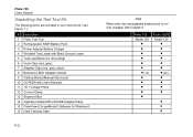
Fluke 125 Model 125 1x Fluke 125/S Model 125 2x • • • Fluke 125 Users Manual Unpacking the Test Tool Kit The following items are included in your test tool kit. (see Figure 1.): # Description 1 Fluke Test Tool 2 Rechargeable NiMH Battery Pack 3 Power Adapter/Battery Charger 4 Shielded Test Leads with Black Ground Leads 5 Test Lead Black (for Grounding) 6 Hook Clips (... RS-232/USB Adapter/Cable 15 FlukeView® ScopeMeter® Software for Windows® 16 Hard Carrying Case 0-2 Note When new, the rechargeable battery pack is not fully charged. See Chapter 2.
Fluke 125 Model 125 1x Fluke 125/S Model 125 2x • • • Fluke 125 Users Manual Unpacking the Test Tool Kit The following items are included in your test tool kit. (see Figure 1.): # Description 1 Fluke Test Tool 2 Rechargeable NiMH Battery Pack 3 Power Adapter/Battery Charger 4 Shielded Test Leads with Black Ground Leads 5 Test Lead Black (for Grounding) 6 Hook Clips (... RS-232/USB Adapter/Cable 15 FlukeView® ScopeMeter® Software for Windows® 16 Hard Carrying Case 0-2 Note When new, the rechargeable battery pack is not fully charged. See Chapter 2.
Fluke 125 Users Manual
Page 14
Fluke 125 Users Manual Safely Using the Test Tool Attention Carefully read the following safety information before using the test tool. Warning To avoid electrical shock, use only Fluke power supply, Model PM8907 (Power Adapter/Battery Charger). 0-4 See explanation in fully automatic mode. To guarantee user safety, all signals should first be measured with AC... this product as unsorted municipal waste. A Caution identifies conditions and actions that may not be found throughout the manual. This ensures that pose hazard(s) to Fluke's website for recycling information.
Fluke 125 Users Manual Safely Using the Test Tool Attention Carefully read the following safety information before using the test tool. Warning To avoid electrical shock, use only Fluke power supply, Model PM8907 (Power Adapter/Battery Charger). 0-4 See explanation in fully automatic mode. To guarantee user safety, all signals should first be measured with AC... this product as unsorted municipal waste. A Caution identifies conditions and actions that may not be found throughout the manual. This ensures that pose hazard(s) to Fluke's website for recycling information.
Fluke 125 Users Manual
Page 15
... 4800 VA: • Use only insulated voltage probes, test leads and adapters supplied with the Test Tool, or indicated as suitable for the Fluke 125 Test Tool. • Before use, inspect voltage probes, test leads and accessories for mechanical damage and replace when damaged. • Remove all...equipped with a terminal for connection to protective ground. Warning To avoid electrical shock or fire: • Use only the power supply, Model PM8907 (Battery Charger / Power Adapter). • Before use check that the selected/indicated voltage range on circuits of more than 42 V peak (30 Vrms)...
... 4800 VA: • Use only insulated voltage probes, test leads and adapters supplied with the Test Tool, or indicated as suitable for the Fluke 125 Test Tool. • Before use, inspect voltage probes, test leads and accessories for mechanical damage and replace when damaged. • Remove all...equipped with a terminal for connection to protective ground. Warning To avoid electrical shock or fire: • Use only the power supply, Model PM8907 (Battery Charger / Power Adapter). • Before use check that the selected/indicated voltage range on circuits of more than 42 V peak (30 Vrms)...
Fluke 125 Users Manual
Page 17
... when it is turned on. Deeply discharged batteries may be empty and must be charged for battery power instructions. Powering the Test Tool Note When battery powered, the battery indicator informs you about the condition of the battery from a standard ac outlet. Preparations for Use At delivery, the batteries may even cause the test tool not...
... when it is turned on. Deeply discharged batteries may be empty and must be charged for battery power instructions. Powering the Test Tool Note When battery powered, the battery indicator informs you about the condition of the battery from a standard ac outlet. Preparations for Use At delivery, the batteries may even cause the test tool not...
Fluke 125 Users Manual
Page 19
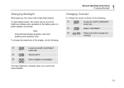
.... Changing Backlight After power-up, the screen has a high bright display. Note Using dimmed display lengthens maximum battery power operation time. To save battery power, the screen has an economic brightness display when operated on the battery pack (no power adapter connected). The high brightness increases when you connect the power adapter. 1 General...
.... Changing Backlight After power-up, the screen has a high bright display. Note Using dimmed display lengthens maximum battery power operation time. To save battery power, the screen has an economic brightness display when operated on the battery pack (no power adapter connected). The high brightness increases when you connect the power adapter. 1 General...
Fluke 125 Users Manual
Page 24
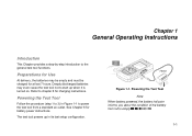
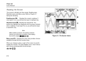
... Displays the waveforms. The bottom line displays the ranges/div and the power indicator (line or battery). Fluke 125 Users Manual Reading the Screen The screen is on , you change a setup, a part of the battery from full to Figure 2-1 during the following. If only input A is on , you about ...the condition of the screen is used to display the choices. Note When battery powered, the battery indicator informs you will see the input A readings only. The area displays one or more menus with choices accessed with the arrow keys:...
... Displays the waveforms. The bottom line displays the ranges/div and the power indicator (line or battery). Fluke 125 Users Manual Reading the Screen The screen is on , you change a setup, a part of the battery from full to Figure 2-1 during the following. If only input A is on , you about ...the condition of the screen is used to display the choices. Note When battery powered, the battery indicator informs you will see the input A readings only. The area displays one or more menus with choices accessed with the arrow keys:...

Fluke 125 Users Manual
Page 77
..., and calibration information, see the Service Manual. Do not use abrasives, solvents, or alcohol. You will find the part number of time, charge the rechargeable battery pack before storing. Chapter 8 Maintaining the Test Tool Introduction This chapter covers basic maintenance procedures that can be performed by the user. It is not...
..., and calibration information, see the Service Manual. Do not use abrasives, solvents, or alcohol. You will find the part number of time, charge the rechargeable battery pack before storing. Chapter 8 Maintaining the Test Tool Introduction This chapter covers basic maintenance procedures that can be performed by the user. It is not...
Fluke 125 Users Manual
Page 78
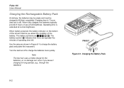
... as shown in Figure 8-1 to fill them completely. Charging the Battery Pack 8-2 Fluke 125 Users Manual Charging the Rechargeable Battery Pack At delivery, the batteries may be empty and must be charged to charge the battery pack and power the instrument. Figure 8-1. When battery powered, the battery indicator on the bottom of the screen informs you leave it...
... as shown in Figure 8-1 to fill them completely. Charging the Battery Pack 8-2 Fluke 125 Users Manual Charging the Rechargeable Battery Pack At delivery, the batteries may be empty and must be charged to charge the battery pack and power the instrument. Figure 8-1. When battery powered, the battery indicator on the bottom of the screen informs you leave it...
Fluke 125 Users Manual
Page 79
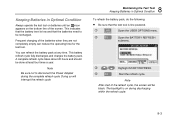
... After start of the refresh cycle, the screen will interrupt the refresh cycle. 8 Maintaining the Test Tool Keeping Batteries in Optimal Condition Always operate the test tool on batteries until an -icon appears on during the complete refresh cycle. You can reduce the operating time for the test... tool. Note Be sure not to be done at any time. Keeping Batteries in Optimal Condition To refresh the battery pack, do the following: • Be sure that the batteries need to disconnect the Power Adapter during discharging within the refresh cycle. 8-3 The backlight is...
... After start of the refresh cycle, the screen will interrupt the refresh cycle. 8 Maintaining the Test Tool Keeping Batteries in Optimal Condition Always operate the test tool on batteries until an -icon appears on during the complete refresh cycle. You can reduce the operating time for the test... tool. Note Be sure not to be done at any time. Keeping Batteries in Optimal Condition To refresh the battery pack, do the following: • Be sure that the batteries need to disconnect the Power Adapter during discharging within the refresh cycle. 8-3 The backlight is...
Fluke 125 Users Manual
Page 80
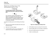
... shock, remove the test leads and probes before replacing the battery pack. Contact your authorized FLUKE Service Center for recycling information. Lift the battery access cover away from the connector. 7. Disconnect the Power Adapter. 3. Replacing the Battery Pack 4. Fluke 125 Users Manual Replacing and Disposing of the battery compartment. 6. Loosen the screw with other solid waste. Remove...
... shock, remove the test leads and probes before replacing the battery pack. Contact your authorized FLUKE Service Center for recycling information. Lift the battery access cover away from the connector. 7. Disconnect the Power Adapter. 3. Replacing the Battery Pack 4. Fluke 125 Users Manual Replacing and Disposing of the battery compartment. 6. Loosen the screw with other solid waste. Remove...
Fluke 125 Users Manual
Page 81
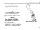
...probe) and the banana-toBNC adapter (BB120). Using and Adjusting 10:1 Scope Probes Note The 10:1 voltage probe VPS40 that the battery pack is always adjusted correctly to adjust other 10:1 scope probes for optimal response. Warning To avoid electrical shock use the BB120...the Test Tool Using and Adjusting 10:1 Scope Probes BB120 Figure 8-3. Adjusting Scope Probes 8-5 Reinstall the battery cover and secure the screw. Note Ensure that is supplied with Fluke 125 is placed in the battery compartment as shown in Figure 8-2. 8. To adjust probes, do the following: • Connect the...
...probe) and the banana-toBNC adapter (BB120). Using and Adjusting 10:1 Scope Probes Note The 10:1 voltage probe VPS40 that the battery pack is always adjusted correctly to adjust other 10:1 scope probes for optimal response. Warning To avoid electrical shock use the BB120...the Test Tool Using and Adjusting 10:1 Scope Probes BB120 Figure 8-3. Adjusting Scope Probes 8-5 Reinstall the battery cover and secure the screw. Note Ensure that is supplied with Fluke 125 is placed in the battery compartment as shown in Figure 8-2. 8. To adjust probes, do the following: • Connect the...
Fluke 125 Users Manual
Page 83
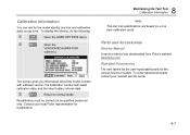
...out by qualified personnel only. Contact your nearest service center. 8-7 Calibration Information You can downloaded from Fluke's website www.fluke.com Standard Accessories The next tables list the user-replaceable parts for the model identity (version and ...calibration data) at any time. e Return to normal mode. The screen gives you information about the model number with software version, the calibration number with latest calibration date, and the latest battery...
...out by qualified personnel only. Contact your nearest service center. 8-7 Calibration Information You can downloaded from Fluke's website www.fluke.com Standard Accessories The next tables list the user-replaceable parts for the model identity (version and ...calibration data) at any time. e Return to normal mode. The screen gives you information about the model number with software version, the calibration number with latest calibration date, and the latest battery...


