
Service Manual
Page 1
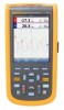
® Fluke 123/124/125 Industrial ScopeMeter Service Manual 4822 872 05398 March 2007 © 2007 Fluke Corporation, All rights reserved. All product names are trademarks of their respective companies.
® Fluke 123/124/125 Industrial ScopeMeter Service Manual 4822 872 05398 March 2007 © 2007 Fluke Corporation, All rights reserved. All product names are trademarks of their respective companies.

Service Manual
Page 3
... in this Manual and on Instrument 1-4 1.2.5 Impaired Safety 1-4 1.2.6 General Safety Information 1-4 Characteristics 2-1 2.1 Introduction...2-3 2.2 Dual Input Oscilloscope 2-3 2.2.1 Vertical...2-3 2.2.2 Horizontal 2-4 2.2.3 Trigger ...2-4 2.2.4 Advanced Scope Functions 2-5 2.3 Dual Input Meter 2-5 2.3.1 Input A and Input B 2-5 2.3.2 Input A ...2-8 2.3.3 Advanced Meter Functions 2-9 2.4 Cursor Readout (Fluke 124, 125 2-10 2.5 Harmonics Measurements (Fluke 125 2-10 2.6 Field Bus Measurements (Fluke 125 2-11 2.7 Miscellaneous 2-11 2.8 Environmental 2-12 2.9 Service and...
... in this Manual and on Instrument 1-4 1.2.5 Impaired Safety 1-4 1.2.6 General Safety Information 1-4 Characteristics 2-1 2.1 Introduction...2-3 2.2 Dual Input Oscilloscope 2-3 2.2.1 Vertical...2-3 2.2.2 Horizontal 2-4 2.2.3 Trigger ...2-4 2.2.4 Advanced Scope Functions 2-5 2.3 Dual Input Meter 2-5 2.3.1 Input A and Input B 2-5 2.3.2 Input A ...2-8 2.3.3 Advanced Meter Functions 2-9 2.4 Cursor Readout (Fluke 124, 125 2-10 2.5 Harmonics Measurements (Fluke 125 2-10 2.6 Field Bus Measurements (Fluke 125 2-11 2.7 Miscellaneous 2-11 2.8 Environmental 2-12 2.9 Service and...
Service Manual
Page 4
Fluke 123/124/125 Service Manual Performance Verification 3-1 3.1 Introduction...3-3 3.2 Equipment Required For Verification 3-3 3.3 How To Verify 3-4 3.4 Display and Backlight Test 3-4 3.5 Input A and Input B Tests 3-5 3.5.1 Input A and B Base Line Jump Test ...and B AC Input Coupling Test 3-19 3.5.12 Input A and B Volts Peak Measurements Test 3-20 3.5.13 Input A and B Phase Measurements Test 3-21 3.5.14 Harmonics (Fluke 125 3-21 3.5.15 Input A and B High Voltage AC/DC Accuracy Test 3-22 3.5.16 Resistance Measurements Test 3-24 3.5.17 Continuity Function Test 3-25 3.5.18 Diode Test...
Fluke 123/124/125 Service Manual Performance Verification 3-1 3.1 Introduction...3-3 3.2 Equipment Required For Verification 3-3 3.3 How To Verify 3-4 3.4 Display and Backlight Test 3-4 3.5 Input A and Input B Tests 3-5 3.5.1 Input A and B Base Line Jump Test ...and B AC Input Coupling Test 3-19 3.5.12 Input A and B Volts Peak Measurements Test 3-20 3.5.13 Input A and B Phase Measurements Test 3-21 3.5.14 Harmonics (Fluke 125 3-21 3.5.15 Input A and B High Voltage AC/DC Accuracy Test 3-22 3.5.16 Resistance Measurements Test 3-24 3.5.17 Continuity Function Test 3-25 3.5.18 Diode Test...
Service Manual
Page 10
Fluke 123/124/125 Service Manual 3-14.Test Tool Screen for NTSC line 262 3-30 3-15.Test Tool Input A to TV Signal Generator Inverted 3-30 3-16.Test Tool Screen for PAL/SECAM line 310 Negative Video 3-31 3-17.Test Tool Screen for NTSC line 262 Negative Video 3-31 4-1.Version & Calibration Screen 4-3 4-2.Display Test Pattern 4-6 4-3.HF Gain Calibration Input Connections 4-7 4-4.5500A Scope Output to Input A 4-9 4-5.5500A Scope Output to Input B 4-10 4-6. Volt Gain Calibration Input Connections
Fluke 123/124/125 Service Manual 3-14.Test Tool Screen for NTSC line 262 3-30 3-15.Test Tool Input A to TV Signal Generator Inverted 3-30 3-16.Test Tool Screen for PAL/SECAM line 310 Negative Video 3-31 3-17.Test Tool Screen for NTSC line 262 Negative Video 3-31 4-1.Version & Calibration Screen 4-3 4-2.Display Test Pattern 4-6 4-3.HF Gain Calibration Input Connections 4-7 4-4.5500A Scope Output to Input A 4-9 4-5.5500A Scope Output to Input B 4-10 4-6. Volt Gain Calibration Input Connections

Service Manual
Page 11
Chapter 1 Introduction and Safety Instructions Title Page 1.1 Introduction to Service Manual 1-3 1.2 Safety ...1-3 1.2.1 Introduction 1-3 1.2.2 Safety Precautions 1-3 1.2.3 Caution and Warning Statements 1-3 1.2.4 Symbols used in this Manual and on Instrument 1-4 1.2.5 Impaired Safety 1-4 1.2.6 General Safety Information 1-4 1-1
Chapter 1 Introduction and Safety Instructions Title Page 1.1 Introduction to Service Manual 1-3 1.2 Safety ...1-3 1.2.1 Introduction 1-3 1.2.2 Safety Precautions 1-3 1.2.3 Caution and Warning Statements 1-3 1.2.4 Symbols used in this Manual and on Instrument 1-4 1.2.5 Impaired Safety 1-4 1.2.6 General Safety Information 1-4 1-1

Service Manual
Page 13
1 Introduction and Safety Instructions 1.1 Introduction to Service Manual 1.1 Introduction to Service Manual The Fluke 123, 124, 125 Industrial Scopemeters (hereafter referred to as 'test tool') offers an extensive and powerful set of measurement...in this Service Manual: Chapter 1. Chapter 3. List of this instrument it is essential that both operating and service personnel follow generally accepted safety procedures in addition to the safety precautions specified in a safe condition. The following information is presented in this manual is only available to Fluke Service Centers due...
1 Introduction and Safety Instructions 1.1 Introduction to Service Manual 1.1 Introduction to Service Manual The Fluke 123, 124, 125 Industrial Scopemeters (hereafter referred to as 'test tool') offers an extensive and powerful set of measurement...in this Service Manual: Chapter 1. Chapter 3. List of this instrument it is essential that both operating and service personnel follow generally accepted safety procedures in addition to the safety precautions specified in a safe condition. The following information is presented in this manual is only available to Fluke Service Centers due...

Service Manual
Page 14
...impaired if, for the safety of the instrument may only be turned off and disconnected from all voltage sources. Fluke 123/124/125 Service Manual 1.2.4 Symbols used in this product as unsorted municipal waste. Capacitors inside the instrument can be gained by components ...obtained through your local FLUKE organization. Go to Fluke's website for recycling information 1.2.5 Impaired Safety Whenever it is likely to life. ...
...impaired if, for the safety of the instrument may only be turned off and disconnected from all voltage sources. Fluke 123/124/125 Service Manual 1.2.4 Symbols used in this product as unsorted municipal waste. Capacitors inside the instrument can be gained by components ...obtained through your local FLUKE organization. Go to Fluke's website for recycling information 1.2.5 Impaired Safety Whenever it is likely to life. ...

Service Manual
Page 18
...;(0.1% +0.04 time/div) Glitch Detection ≥40 ns @ 20 ns to 5 ms/div ≥200 ns @ 10 ms to ground Resolution Vertical Accuracy Max. Fluke 123/124/125 Service Manual Sensitivity 5 mV to 400Hz 8 bit ±(1% + 0.05 range/div) ±4 divisions Max. Base Line Jump Normal & Single mode After changing time base or...
...;(0.1% +0.04 time/div) Glitch Detection ≥40 ns @ 20 ns to 5 ms/div ≥200 ns @ 10 ms to ground Resolution Vertical Accuracy Max. Fluke 123/124/125 Service Manual Sensitivity 5 mV to 400Hz 8 bit ±(1% + 0.05 range/div) ±4 divisions Max. Base Line Jump Normal & Single mode After changing time base or...

Service Manual
Page 20
..., 500V, 1250V Accuracy for Continuous Autoset 15Hz (1Hz) to -Peak 5% of full scale 10% of any signal crest factor. Move influence ±6 counts max. Fluke 123/124/125 Service Manual Common Mode Rejection (CMRR) >100 dB @ DC >60 dB @ 50, 60, or 400 Hz Full Scale Reading 5000 counts Move influence ±6 counts...
..., 500V, 1250V Accuracy for Continuous Autoset 15Hz (1Hz) to -Peak 5% of full scale 10% of any signal crest factor. Move influence ±6 counts max. Fluke 123/124/125 Service Manual Common Mode Rejection (CMRR) >100 dB @ DC >60 dB @ 50, 60, or 400 Hz Full Scale Reading 5000 counts Move influence ±6 counts...

Service Manual
Page 22
Fluke 123/124/125 Service Manual Crest Factor (CREST) Range Accuracy Full Scale Reading Phase Modes Range Accuracy Resolution Power (Fluke 125) Configurations Power Factor (PF) Range Watt Full Scale reading VA Full Scale Reading VA Reactive (VAR) Full Scale Reading VPWM (Fluke 125) Purpose Principle Accuracy 2.3.2 Input ...effective voltage based on the average value of samples over a whole number of periods of the fundamental frequency as Vrms for sinewave signals 50Ω (Fluke 125), 500Ω, 5 kΩ, 50 kΩ, 500 kΩ, 5 MΩ, 30 MΩ ±(0.6% +5 counts) 5000 counts 3000 ...
Fluke 123/124/125 Service Manual Crest Factor (CREST) Range Accuracy Full Scale Reading Phase Modes Range Accuracy Resolution Power (Fluke 125) Configurations Power Factor (PF) Range Watt Full Scale reading VA Full Scale Reading VA Reactive (VAR) Full Scale Reading VPWM (Fluke 125) Purpose Principle Accuracy 2.3.2 Input ...effective voltage based on the average value of samples over a whole number of periods of the fundamental frequency as Vrms for sinewave signals 50Ω (Fluke 125), 500Ω, 5 kΩ, 50 kΩ, 500 kΩ, 5 MΩ, 30 MΩ ±(0.6% +5 counts) 5000 counts 3000 ...

Service Manual
Page 24
...), 33st ±(10 % + 10 counts) Frequency of Readout (in ROLL mode, instrument in Amp and Watt) ± 10 % Time base fixed 2-10 Fluke 123/124/125 Service Manual 2.4 Cursor Readout (Fluke 124, 125) Sources A,B Single Vertical Line Average, Min and Max Readout. Average, Min, Max and Time from Start of Readout (in TRENDPLOT mode...
...), 33st ±(10 % + 10 counts) Frequency of Readout (in ROLL mode, instrument in Amp and Watt) ± 10 % Time base fixed 2-10 Fluke 123/124/125 Service Manual 2.4 Cursor Readout (Fluke 124, 125) Sources A,B Single Vertical Line Average, Min and Max Readout. Average, Min, Max and Time from Start of Readout (in TRENDPLOT mode...
Service Manual
Page 26
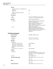
... Vrms Cat III up to 140 °F) noncondensing 95% 75% 45% noncondensing 5 km (16 400 feet) Max. Fluke 123/124/125 Service Manual Memory Number of Screen + Setup Memories Fluke 123 Fluke 124 Number of Data Set memories Fluke 125 Mechanical Size Weight Interface To Printer To PC 10 20 20 232 x 115 x 50 mm (9.1 x 4.5 x 2 in...
... Vrms Cat III up to 140 °F) noncondensing 95% 75% 45% noncondensing 5 km (16 400 feet) Max. Fluke 123/124/125 Service Manual Memory Number of Screen + Setup Memories Fluke 123 Fluke 124 Number of Data Set memories Fluke 125 Mechanical Size Weight Interface To Printer To PC 10 20 20 232 x 115 x 50 mm (9.1 x 4.5 x 2 in...

Service Manual
Page 33
... test tool is in the verification procedures is based on the same measurement principles; The test tool should be performed by qualified service personnel only. For example: the duty cycle, pulse width, and frequency measurement are valid for ambient temperatures between 18 °C...values given here are based on the specifications, listed in this Service Manual. Because of the highly integrated design of the test tool, it is necessary. The Performance Verification Procedure is not available, you have a Fluke 5500A with 600 MHz option can substitute another calibrator as long...
... test tool is in the verification procedures is based on the same measurement principles; The test tool should be performed by qualified service personnel only. For example: the duty cycle, pulse width, and frequency measurement are valid for ambient temperatures between 18 °C...values given here are based on the specifications, listed in this Service Manual. Because of the highly integrated design of the test tool, it is necessary. The Performance Verification Procedure is not available, you have a Fluke 5500A with 600 MHz option can substitute another calibrator as long...

Service Manual
Page 34
.... 3.3 How To Verify Verification procedures for the display function and measure functions follow. the test pattern as follows to maximum. 5. Fluke 123/124/125 Service Manual These video signals must be installed. • Allow the 5500A to satisfy its specified warm-up period. • For each procedure... that the test tool can be 3-4 The test tool shows Contrast (CL 0100):MANUAL 9. Then select maximum backlight brightness again. This is set to test the display and the backlight: 1. Fluke 123: press and verify that the backlight brightness is caused by the higher vertical and...
.... 3.3 How To Verify Verification procedures for the display function and measure functions follow. the test pattern as follows to maximum. 5. Fluke 123/124/125 Service Manual These video signals must be installed. • Allow the 5500A to satisfy its specified warm-up period. • For each procedure... that the test tool can be 3-4 The test tool shows Contrast (CL 0100):MANUAL 9. Then select maximum backlight brightness again. This is set to test the display and the backlight: 1. Fluke 123: press and verify that the backlight brightness is caused by the higher vertical and...
Service Manual
Page 36
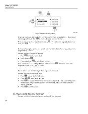
... to reset the test tool: • Press to turn the test tool off. • Press and hold . • Press and release to confirm the selection; Fluke 123/124/125 Service Manual Figure 3-2. Menu item selection ST7968.WMF If an item is selected, it is marked by performing a RESET.
... to reset the test tool: • Press to turn the test tool off. • Press and hold . • Press and release to confirm the selection; Fluke 123/124/125 Service Manual Figure 3-2. Menu item selection ST7968.WMF If an item is selected, it is marked by performing a RESET.

Service Manual
Page 38
... tool display. 8. The allowed difference is indicated by the trigger icon ( ). 6. Set the 5500A to the same position after changing the sensitivity. Fluke 123/124/125 Service Manual Observe the Input B trace, and check to see if it is set to Operate (OPR). 4. adjust the trigger level and verify that the signal... is well triggered. Set the 5500A to source a 25 MHz (Fluke 123) or 40 MHz (Fluke 124/125) leveled sine wave of the sine ...
... tool display. 8. The allowed difference is indicated by the trigger icon ( ). 6. Set the 5500A to the same position after changing the sensitivity. Fluke 123/124/125 Service Manual Observe the Input B trace, and check to see if it is set to Operate (OPR). 4. adjust the trigger level and verify that the signal... is well triggered. Set the 5500A to source a 25 MHz (Fluke 123) or 40 MHz (Fluke 124/125) leveled sine wave of the sine ...
Service Manual
Page 40
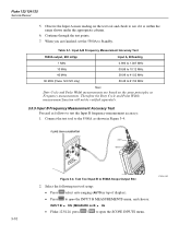
... open the SCOPE INPUTS menu. 3-10 Continue through the test points. 7. Observe the Input A main reading on B: Hz • Fluke 123/124: press / to open the INPUT B MEASUREMENTS menu, and choose: INPUT B: ON | MEASURE on the test tool and ...Input A,B Frequency Measurement Accuracy Test 5500A output, 600 mVpp Input A, B Reading 1 MHz 10 MHz 40 MHz 60 MHz (Fluke 124/125 only) 0.993 to 1.007 MHz 09.88 to 10.12 MHz 38.98 to 41.02 MHz 58.48 ... 3-1. Select the following test tool setup: • Press select auto ranging (AUTO in Figure 3-4. Fluke 123/124/125 Service Manual 5.
... open the SCOPE INPUTS menu. 3-10 Continue through the test points. 7. Observe the Input A main reading on B: Hz • Fluke 123/124: press / to open the INPUT B MEASUREMENTS menu, and choose: INPUT B: ON | MEASURE on the test tool and ...Input A,B Frequency Measurement Accuracy Test 5500A output, 600 mVpp Input A, B Reading 1 MHz 10 MHz 40 MHz 60 MHz (Fluke 124/125 only) 0.993 to 1.007 MHz 09.88 to 10.12 MHz 38.98 to 41.02 MHz 58.48 ... 3-1. Select the following test tool setup: • Press select auto ranging (AUTO in Figure 3-4. Fluke 123/124/125 Service Manual 5.
Service Manual
Page 42
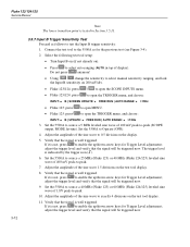
...for the previous test (see Figure 3-4). 2. Verify that the signal will be triggered now. 9. Adjust the amplitude of display). Fluke 123/124/125 Service Manual Note The lower transition point is well triggered. Connect the test tool to the 5500A as follows to -peak (SCOPE output, MODE...; Do not press anymore! • Using change the sensitivity to select manual sensitivity ranging, and lock the Input B sensitivity on 200 mV/div. • Fluke 123/124: press / to open the SCOPE INPUTS menu. • Fluke 123/124: press to open the TRIGGER menu, and choose: INPUT: ...
...for the previous test (see Figure 3-4). 2. Verify that the signal will be triggered now. 9. Adjust the amplitude of display). Fluke 123/124/125 Service Manual Note The lower transition point is well triggered. Connect the test tool to the 5500A as follows to -peak (SCOPE output, MODE...; Do not press anymore! • Using change the sensitivity to select manual sensitivity ranging, and lock the Input B sensitivity on 200 mV/div. • Fluke 123/124: press / to open the SCOPE INPUTS menu. • Fluke 123/124: press to open the TRIGGER menu, and choose: INPUT: ...

Service Manual
Page 44
... at step 12. 16. Set the 5500A to open the SMOOTH menu, and choose : WAVEFORM: NORMAL 3. To repeat the test, start at step 3. 7. Fluke 123/124/125 Service Manual • Using select positive slope triggering (trigger icon ). • Using set the trigger level to +2 divisions from the screen center. For positive slope triggering...
... at step 12. 16. Set the 5500A to open the SMOOTH menu, and choose : WAVEFORM: NORMAL 3. To repeat the test, start at step 3. 7. Fluke 123/124/125 Service Manual • Using select positive slope triggering (trigger icon ). • Using set the trigger level to +2 divisions from the screen center. For positive slope triggering...
Service Manual
Page 46
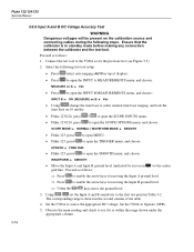
... the calibrator is within the range shown under the appropriate column. 3-16 Set the 5500A to the first test point in top of the table. 4. Fluke 123/124/125 Service Manual 3.5.9 Input A and B DC Voltage Accuracy Test WARNING Dangerous voltages will be present on 10 ms/div. •...
... the calibrator is within the range shown under the appropriate column. 3-16 Set the 5500A to the first test point in top of the table. 4. Fluke 123/124/125 Service Manual 3.5.9 Input A and B DC Voltage Accuracy Test WARNING Dangerous voltages will be present on 10 ms/div. •...


