Technical Reference
Page 12
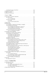
...28 3.4.8 Connecting the Printer to the Host PC / POS Terminal 3-30 3.4.8.1 Serial Interface model 3-31 3.4.8.2 Parallel Interface Models 3-31 3.4.8.3 USB Interface Models 3-31 3.4.8.4 Ethernet interface 3-33 3.4.8.5 Connecting a Drawer 3-34 3.5 Install a Printer Driver in the Host...up 3-34 3.5.1.2 Package contents of EPSON OPOS ADK 3-37 3.5.2 Advanced Printer Driver (APD 3-38 3.5.2.1 Installing and Setting Up 3-38 3.6 Self Test 3-40 3.6.1 Self Test Procedure 3-40 Chapter 4 Troubleshooting 4.1 LED Blinking Pattern 4-1 4.1.1 Error Types 4-1 4.1.1.1 Errors that automatically recover ...
...28 3.4.8 Connecting the Printer to the Host PC / POS Terminal 3-30 3.4.8.1 Serial Interface model 3-31 3.4.8.2 Parallel Interface Models 3-31 3.4.8.3 USB Interface Models 3-31 3.4.8.4 Ethernet interface 3-33 3.4.8.5 Connecting a Drawer 3-34 3.5 Install a Printer Driver in the Host...up 3-34 3.5.1.2 Package contents of EPSON OPOS ADK 3-37 3.5.2 Advanced Printer Driver (APD 3-38 3.5.2.1 Installing and Setting Up 3-38 3.6 Self Test 3-40 3.6.1 Self Test Procedure 3-40 Chapter 4 Troubleshooting 4.1 LED Blinking Pattern 4-1 4.1.1 Error Types 4-1 4.1.1.1 Errors that automatically recover ...
Technical Reference
Page 21
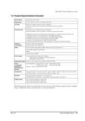
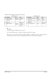
... 34 °C {93°F} or higher, there are 2 types. Partial cut (cutting with one of the following : Japanese Kanji, Simplified Chinese, Traditional Chinese, Thai characters, or Korean characters. TM-U220 Technical Reference Guide 1.4 Product Specifications Overview Print method Paper width Cut type Character sets serial impact dot matrix 76 mm / 69.5 mm / 57.5 mm {3.00...
... 34 °C {93°F} or higher, there are 2 types. Partial cut (cutting with one of the following : Japanese Kanji, Simplified Chinese, Traditional Chinese, Thai characters, or Korean characters. TM-U220 Technical Reference Guide 1.4 Product Specifications Overview Print method Paper width Cut type Character sets serial impact dot matrix 76 mm / 69.5 mm / 57.5 mm {3.00...

Technical Reference
Page 37
... Method A TM printer can print and be used, an IP setting tool for the Ethernet specification, a USB device driver, and a logo registration utility for controlling the printer, which enables...EPSON OPOS ADK 3. Windows printer driver (EPSON Advanced Printer Driver) 2. Note: The statusAPI is supplied exclusively by StatusAPI with the TM printer under the Windows standard printer driver environment. ESC/POS commands Depending on the driver or interface to have bi-directional communication with a programming language such as paper cutting and drawer opening. ❏ Font type...
... Method A TM printer can print and be used, an IP setting tool for the Ethernet specification, a USB device driver, and a logo registration utility for controlling the printer, which enables...EPSON OPOS ADK 3. Windows printer driver (EPSON Advanced Printer Driver) 2. Note: The statusAPI is supplied exclusively by StatusAPI with the TM printer under the Windows standard printer driver environment. ESC/POS commands Depending on the driver or interface to have bi-directional communication with a programming language such as paper cutting and drawer opening. ❏ Font type...
Technical Reference
Page 44
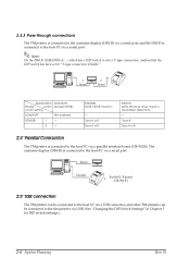
..., Visual C, Visual Basic, MSComm) - Type B Type A or B 2.4 Parallel Connection The TM printer is connected to the first printer via a parallel interface board (UB-P02II). The customer display (DM-D) is connected to the host PC via a serial port. 2.5 USB connection The TM printer can be connected to the host PC via a USB connector, and other TM printers can be connected to the...
..., Visual C, Visual Basic, MSComm) - Type B Type A or B 2.4 Parallel Connection The TM printer is connected to the first printer via a parallel interface board (UB-P02II). The customer display (DM-D) is connected to the host PC via a serial port. 2.5 USB connection The TM printer can be connected to the host PC via a USB connector, and other TM printers can be connected to the...
Technical Reference
Page 62
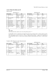
...Offline (DIP Switch 2) SW Function On 1 Print column selection 42/35 2 Reserved Type A, B (Auto cutter enable/ Fixed to On disable) 3~7 Reserved - 8 Pin 31 reset signal Used Off 40/33 Type D Fixed to Off Fixed to adjust DIP switch "Serial interface selection" function and ...Memory switch "Serial communication condition". 3-16 Setup Rev. Parallel / USB / Ethernet model (Except serial) (DIP Switch 1) SW Function On Off ...
...Offline (DIP Switch 2) SW Function On 1 Print column selection 42/35 2 Reserved Type A, B (Auto cutter enable/ Fixed to On disable) 3~7 Reserved - 8 Pin 31 reset signal Used Off 40/33 Type D Fixed to Off Fixed to adjust DIP switch "Serial interface selection" function and ...Memory switch "Serial communication condition". 3-16 Setup Rev. Parallel / USB / Ethernet model (Except serial) (DIP Switch 1) SW Function On Off ...
Technical Reference
Page 63
...switch 1-1 should be fixed to Off DIP switch Note: When the printer has a data receive error, the printer prints "?." The right side up printing mode is a mode used for a printer that is "Right side up printing" ?" (page 5-10). Parallel / USB / Ethernet model (Except serial) (DIP Switch 1) SW Function ...wall. Type D Fixed to Off Fixed to Off Not used Fixed to On disable) 3 Reserved - 4 Pin 31 reset signal Used 5~8 Reserved - Regardless of the setting of DIP switch 1-1, if you want to perform right side up printing, DIP switch 1-2 must be turned off . TM-U220 Technical...
...switch 1-1 should be fixed to Off DIP switch Note: When the printer has a data receive error, the printer prints "?." The right side up printing mode is a mode used for a printer that is "Right side up printing" ?" (page 5-10). Parallel / USB / Ethernet model (Except serial) (DIP Switch 1) SW Function ...wall. Type D Fixed to Off Fixed to Off Not used Fixed to On disable) 3 Reserved - 4 Pin 31 reset signal Used 5~8 Reserved - Regardless of the setting of DIP switch 1-1, if you want to perform right side up printing, DIP switch 1-2 must be turned off . TM-U220 Technical...
Technical Reference
Page 76
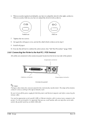
...Tighten the two screws. 8. Install roll paper 10. Execute the self test to confirm the cutter action. (See "Self Test Procedure" (page 3-40)) 3.4.8 Connecting the Printer to the Host PC / POS Terminal All cables are connected to turn off the power supply for the serial interface model printer. For the...to the right, as shown. 6. Partial cut Full cut (default), you have to adjust the dowel to the type of the printer. You need an appropriate serial, parallel, USB, or Ethernet interface cable to connect your computer to left as shown. Drawer kick connector FG FG DK DC24V ...
...Tighten the two screws. 8. Install roll paper 10. Execute the self test to confirm the cutter action. (See "Self Test Procedure" (page 3-40)) 3.4.8 Connecting the Printer to the Host PC / POS Terminal All cables are connected to turn off the power supply for the serial interface model printer. For the...to the right, as shown. 6. Partial cut Full cut (default), you have to adjust the dowel to the type of the printer. You need an appropriate serial, parallel, USB, or Ethernet interface cable to connect your computer to left as shown. Drawer kick connector FG FG DK DC24V ...
