Installation Guide
Page 4
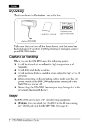
...locations that are unstable or are turned off. ❏ Do not drop the DM-D500, because you find anything missing or damaged, contact your DM-D500 dealer. If you may damage the builtin vacuum fluorescent display. English Unpacking The items shown in illustration 1 are in the box. 1 installation... manual warranty card (201 model only) display (DM-D500) Make sure that you have all the items shown, and that the power switch of the DM-D500 and printers connected to the DM-D500 are...
...locations that are unstable or are turned off. ❏ Do not drop the DM-D500, because you find anything missing or damaged, contact your DM-D500 dealer. If you may damage the builtin vacuum fluorescent display. English Unpacking The items shown in illustration 1 are in the box. 1 installation... manual warranty card (201 model only) display (DM-D500) Make sure that you have all the items shown, and that the power switch of the DM-D500 and printers connected to the DM-D500 are...

Installation Guide
Page 5
... code: C8233610200). You can attach the DM-D500 directly to these printers using the "DM-D stand unit for TM printers" (DP-505). (See page 14.) ❏ Other TM printers. You can attach the DM-D500 to the DM-D stand using the "DM-D pole unit for DM-D500" (DP-501). You can attach the DM-D500 to the DM-D500 without an additional board. If the serial...
... code: C8233610200). You can attach the DM-D500 directly to these printers using the "DM-D stand unit for TM printers" (DP-505). (See page 14.) ❏ Other TM printers. You can attach the DM-D500 to the DM-D stand using the "DM-D pole unit for DM-D500" (DP-501). You can attach the DM-D500 to the DM-D500 without an additional board. If the serial...
Installation Guide
Page 6
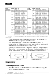
...2XT0 010001 and higher AQS0 010001 and higher *1: If your TM printer is not listed above, it can be connected to the DM-D500 without an additional board. 2 3 blue seal Assembling scribed square Attaching to the IR Series The DM-D500 can be connected to the IR Series using it can be ...attached directly to the DM-D500 without any special modifications. If your printer is connected to the TM printer, purchase and install the latest model of the TM printer or the UB-S01 board has a blue seal or a scribed square (as shown in ...
...2XT0 010001 and higher AQS0 010001 and higher *1: If your TM printer is not listed above, it can be connected to the DM-D500 without an additional board. 2 3 blue seal Assembling scribed square Attaching to the IR Series The DM-D500 can be connected to the IR Series using it can be ...attached directly to the DM-D500 without any special modifications. If your printer is connected to the TM printer, purchase and install the latest model of the TM printer or the UB-S01 board has a blue seal or a scribed square (as shown in ...
Installation Guide
Page 8
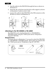
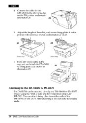
... The items shown in illustration 10. 8 9 10 Attaching to the TM-H5000II or TM-J8000 The DM-D500 can be attached directly to a TM-H5000II or TM-J8000 printer. Connect the cable for the DM-D500 to the DM connector on the support as shown in illustration 9 until you feel it click. 5. Insert the tab on...
... The items shown in illustration 10. 8 9 10 Attaching to the TM-H5000II or TM-J8000 The DM-D500 can be attached directly to a TM-H5000II or TM-J8000 printer. Connect the cable for the DM-D500 to the DM connector on the support as shown in illustration 9 until you feel it click. 5. Insert the tab on...
Installation Guide
Page 9
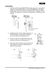
Pass the cable for extension 2. Insert the tab on the base into the hole on the TM printer, and secure it click. 15 16 DM-D500 Installation Guide 7 Attach the base to the DM-D500 as shown in illustration 15. 4. When using support B for extension, insert the tab on support B into the hole... feel it with the 14 screws as shown in illustration 13 until you feel it click. 12 13 when using support B for the DM-D500 through support C, and attach support C to the setting position on support C as shown in illustration 14. 3. English Assembling 1. Pass the cable ...
Pass the cable for extension 2. Insert the tab on the base into the hole on the TM printer, and secure it click. 15 16 DM-D500 Installation Guide 7 Attach the base to the DM-D500 as shown in illustration 15. 4. When using support B for extension, insert the tab on support B into the hole... feel it with the 14 screws as shown in illustration 13 until you feel it click. 12 13 when using support B for the DM-D500 through support C, and attach support C to the setting position on support C as shown in illustration 14. 3. English Assembling 1. Pass the cable ...

Installation Guide
Page 10
Attaching to the TM-U375 or TM-U950 The DM-D500 can be attached directly to the DM 17 connector on the TM printer as shown in illustrations 18, 19, or 20 are packed with the "DM-D pole unit for TM printers (Type A)" (DP-502). 18 19 rubber feet rubber feet (square) ... C support B for TM printers (Type A)" (DP-502). These items are used to attach a DM-D500 to a TM-U375 or TM-U950 printer. English 5. Connect the cable for the DM-D500 to a TM-U375 or TM-U950 printer using the "DM-D pole unit for extension fixing plate A 8 DM-D500 Installation Guide Required items The ...
Attaching to the TM-U375 or TM-U950 The DM-D500 can be attached directly to the DM 17 connector on the TM printer as shown in illustrations 18, 19, or 20 are packed with the "DM-D pole unit for TM printers (Type A)" (DP-502). 18 19 rubber feet rubber feet (square) ... C support B for TM printers (Type A)" (DP-502). These items are used to attach a DM-D500 to a TM-U375 or TM-U950 printer. English 5. Connect the cable for the DM-D500 to a TM-U375 or TM-U950 printer using the "DM-D pole unit for extension fixing plate A 8 DM-D500 Installation Guide Required items The ...

Installation Guide
Page 11
... the cable for the DM-D500 through support C, and attach support C to the printer as shown in illustration 25. Pass the cable for the DM-D500 through the 25 hole on support C as shown in illustration 23 or 24. 23 24 [TM-U375] [TM-U950] 3. Attach the rubber feet to the DM-D500 as shown in illustration...
... the cable for the DM-D500 through support C, and attach support C to the printer as shown in illustration 25. Pass the cable for the DM-D500 through the 25 hole on support C as shown in illustration 23 or 24. 23 24 [TM-U375] [TM-U950] 3. Attach the rubber feet to the DM-D500 as shown in illustration...
Installation Guide
Page 12
...support, and attach the DM-D500 to the printer with screws as shown in illustration 27 or 28. 27 28 [TM-U375] [TM-U950] 6. Adjust the length of the TM-H6000 or TM-U675. You can slide the display freely. 10 DM-D500 Installation Guide Connect the cable for the DM-D500 to a TM-H6000 ...or TM-U675 printer using the "DM-D pole unit for TM printers (Type A)" (DP-502). Attaching to the TM-H6000 or TM-U675 The...
...support, and attach the DM-D500 to the printer with screws as shown in illustration 27 or 28. 27 28 [TM-U375] [TM-U950] 6. Adjust the length of the TM-H6000 or TM-U675. You can slide the display freely. 10 DM-D500 Installation Guide Connect the cable for the DM-D500 to a TM-H6000 ...or TM-U675 printer using the "DM-D pole unit for TM printers (Type A)" (DP-502). Attaching to the TM-H6000 or TM-U675 The...
Installation Guide
Page 13
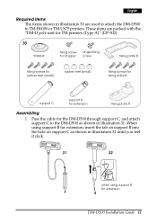
... support B for extension fixing plate A Assembling 1. These items are used to attach the DM-D500 to the DM-D500 as shown in illustration 31. English Required items The items shown in illustration 30 are packed with the "DM-D pole unit for TM printers (Type A)" (DP-502). 30 stopper fixing screw for stopper angle fixing screw fixing...
... support B for extension fixing plate A Assembling 1. These items are used to attach the DM-D500 to the DM-D500 as shown in illustration 31. English Required items The items shown in illustration 30 are packed with the "DM-D pole unit for TM printers (Type A)" (DP-502). 30 stopper fixing screw for stopper angle fixing screw fixing...

Installation Guide
Page 14
Connect the cable for the DM-D500 through the hole on the TM printer as 35 shown in illustration 36. 6. Pass the cable for the DM-D500 to the DM connector on fixing plate A, and fix the cable at the bottom as shown in illustration 35. 5. Fixing plate A can be attached on the ...stopper into the holes of the printer.) 36 37 12 DM-D500 Installation Guide Attach the rubber feet to the right side of fixing plate B. When you attach the stopper, insert the projections on either ...
Connect the cable for the DM-D500 through the hole on the TM printer as 35 shown in illustration 36. 6. Pass the cable for the DM-D500 to the DM connector on fixing plate A, and fix the cable at the bottom as shown in illustration 35. 5. Fixing plate A can be attached on the ...stopper into the holes of the printer.) 36 37 12 DM-D500 Installation Guide Attach the rubber feet to the right side of fixing plate B. When you attach the stopper, insert the projections on either ...
Installation Guide
Page 16
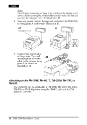
..., TM-U230, TM-T90, or TM-L90 The DM-D500 can open if the position of the display is not correct. Attaching to a TM-T88II, TM-U210, TM-U230, TM-T90, or TM-L90 printer using the "DM-D pole unit for TM printers" (DP-505). 14 DM-D500 Installation Guide Before securing the position of the... printer. English Note: The roll paper cover may not ...
..., TM-U230, TM-T90, or TM-L90 The DM-D500 can open if the position of the display is not correct. Attaching to a TM-T88II, TM-U210, TM-U230, TM-T90, or TM-L90 printer using the "DM-D pole unit for TM printers" (DP-505). 14 DM-D500 Installation Guide Before securing the position of the... printer. English Note: The roll paper cover may not ...
Installation Guide
Page 17
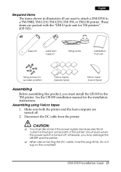
... the host computer are used to attach a DM-D500 to a TM-T88II, TM-U210, TM-U230, TM-T90, or TM-L90 printer. otherwise, you must disconnect the power supply because electrical current is flowing in some parts of the printer circuit even when the power switch is turned off . 2. CAUTION: ❏ You must install... the UB-S09 in the TM printer. DM-D500 Installation Guide 15 English Required items The items shown in illustration 45 are turned off ; Do not tug on the cord itself. See the UB-...
... the host computer are used to attach a DM-D500 to a TM-T88II, TM-U210, TM-U230, TM-T90, or TM-L90 printer. otherwise, you must disconnect the power supply because electrical current is flowing in some parts of the printer circuit even when the power switch is turned off . 2. CAUTION: ❏ You must install... the UB-S09 in the TM printer. DM-D500 Installation Guide 15 English Required items The items shown in illustration 45 are turned off ; Do not tug on the cord itself. See the UB-...

Installation Guide
Page 19
... CAUTION: Do not connect this connector to 11 Attaching position for display (seen from the front of the printer) Right side Left side Both sides 3 1 49 50 5 8 6 10 4 2 11 9 7 6. Connect the cable for your particular printer. (The positioning numbers of the fixing plate. DM-D500 Installation Guide 17 English 5. See the table below to find...
... CAUTION: Do not connect this connector to 11 Attaching position for display (seen from the front of the printer) Right side Left side Both sides 3 1 49 50 5 8 6 10 4 2 11 9 7 6. Connect the cable for your particular printer. (The positioning numbers of the fixing plate. DM-D500 Installation Guide 17 English 5. See the table below to find...

Installation Guide
Page 20
...the power supply to a desk or other TM printers, the DM-D500 can be attached to the TM printer. Secure the fixing plate where you want it vertically.) 52 9. Set the printer so that no rubber foot on the rear side of the printer is placed on the fixing plate. (See the...mounting position for each TM printer.) Printer type TM-T88II TM-U210/U230/T90/L90 Mounting positions for TM printers (Type A)" (DP-502) and screws or Velcro tapes. 18 DM-D500 Installation Guide English 8. Attaching to Other TM Printers When using Velcro tapes." Place the TM printer on the Velcro tape. ...
...the power supply to a desk or other TM printers, the DM-D500 can be attached to the TM printer. Secure the fixing plate where you want it vertically.) 52 9. Set the printer so that no rubber foot on the rear side of the printer is placed on the fixing plate. (See the...mounting position for each TM printer.) Printer type TM-T88II TM-U210/U230/T90/L90 Mounting positions for TM printers (Type A)" (DP-502) and screws or Velcro tapes. 18 DM-D500 Installation Guide English 8. Attaching to Other TM Printers When using Velcro tapes." Place the TM printer on the Velcro tape. ...

Installation Guide
Page 21
English Required items The items shown in illustration 54 are packed with other TM printers. Attach Velcro tapes to the DM-D500 as shown in illustration 57 until you feel it click. 56 57 when using Velcro tapes 1. When using support B for extension, insert the tab... on support B into the hole on support C as shown in illustration 55. 2. These items are used when the DM-D500 is used with the "DM-D pole unit for TM printers (Type A)" (DP-502). 54 fixing plate A Velcro tapes Velcro tapes fixing screws for wood position support C support B (for extension) ...
English Required items The items shown in illustration 54 are packed with other TM printers. Attach Velcro tapes to the DM-D500 as shown in illustration 57 until you feel it click. 56 57 when using Velcro tapes 1. When using support B for extension, insert the tab... on support B into the hole on support C as shown in illustration 55. 2. These items are used when the DM-D500 is used with the "DM-D pole unit for TM printers (Type A)" (DP-502). 54 fixing plate A Velcro tapes Velcro tapes fixing screws for wood position support C support B (for extension) ...

Installation Guide
Page 22
... 2 and 3 in illustration 60. 6. Connect the cable for the DM-D500 through the hole on the TM printer as 58 shown in illustration 61. 3. Peel off the Velcro tapes, and attach the display to fixing plate A. 20 DM-D500 Installation Guide Pass the cable for the DM-D500 to the DC connector on fixing plate A, and fix the...
... 2 and 3 in illustration 60. 6. Connect the cable for the DM-D500 through the hole on the TM printer as 58 shown in illustration 61. 3. Peel off the Velcro tapes, and attach the display to fixing plate A. 20 DM-D500 Installation Guide Pass the cable for the DM-D500 to the DC connector on fixing plate A, and fix the...

Installation Guide
Page 23
... base plate extension cable for DM-D500" (DP-501). English Attaching to the DM-D Stand The DM-D500 can be connected to a TM printer or be attached directly to the DM-D stand using the DM-D stand. The DM-D500 with the DM-D stand can be used to attach the DM-D500 to raise the height of the DM-D500. Also, another optional extension support (DP...
... base plate extension cable for DM-D500" (DP-501). English Attaching to the DM-D Stand The DM-D500 can be connected to a TM printer or be attached directly to the DM-D stand using the DM-D stand. The DM-D500 with the DM-D stand can be used to attach the DM-D500 to raise the height of the DM-D500. Also, another optional extension support (DP...

Installation Guide
Page 24
... lines) 66 inch-type millimeter-type Jumper settings Set the jumpers on the DM-D stand as a standalone. (TM printer is not connected.) 22 DM-D500 Installation Guide computer connector display connector printer connector 65 power supply unit connector extension cable connector Note: The DM-D stand comes with inch-type hexagonal lock screws installed to secure the interface...
... lines) 66 inch-type millimeter-type Jumper settings Set the jumpers on the DM-D stand as a standalone. (TM printer is not connected.) 22 DM-D500 Installation Guide computer connector display connector printer connector 65 power supply unit connector extension cable connector Note: The DM-D stand comes with inch-type hexagonal lock screws installed to secure the interface...

Installation Guide
Page 27
... cable connector 74 extension cable for the printer to the printer connector on the printer as a standalone, go to fasten them. 73 printer 6. If not using the extension cable, connect it (with the arrow mark up) to the extension cable connector indicated with the DM-D stand for power supply, go to... illustration 73. then connect the other end to the power connector on both ends of the printer interface cable for power supply DM-D500 Installation Guide 25 If using the DM stand with the printer, connect one end of the cable to step 7. When using the unit as shown in ...
... cable connector 74 extension cable for the printer to the printer connector on the printer as a standalone, go to fasten them. 73 printer 6. If not using the extension cable, connect it (with the arrow mark up) to the extension cable connector indicated with the DM-D stand for power supply, go to... illustration 73. then connect the other end to the power connector on both ends of the printer interface cable for power supply DM-D500 Installation Guide 25 If using the DM stand with the printer, connect one end of the cable to step 7. When using the unit as shown in ...

Installation Guide
Page 30
... XON/XOFF is effective only when the DM-D500 is connected to a TM printer, be sure that the transmission speed matches that of DIP switches. English DIP Switch DIP Switch Functions The DM-D500 has two groups of the printer. 28 DM-D500 Installation Guide The functions of the DIP... Transmission speed (bps) 2400 4800 9600 19200 38400 57600 115200 *When the DM-D500 is connected as follows: DIP switch 1 DSW1 No. 1-1 1-2 1-3 1-4 1-5 1-6 1-7 1-8 Function Data receive error Hand shaking Data length Parity on or off Parity type Change transmission speed ON OFF Ignored Displays "?"
... XON/XOFF is effective only when the DM-D500 is connected to a TM printer, be sure that the transmission speed matches that of DIP switches. English DIP Switch DIP Switch Functions The DM-D500 has two groups of the printer. 28 DM-D500 Installation Guide The functions of the DIP... Transmission speed (bps) 2400 4800 9600 19200 38400 57600 115200 *When the DM-D500 is connected as follows: DIP switch 1 DSW1 No. 1-1 1-2 1-3 1-4 1-5 1-6 1-7 1-8 Function Data receive error Hand shaking Data length Parity on or off Parity type Change transmission speed ON OFF Ignored Displays "?"
