

User Manual
Page 10
..., hard disk, or network server. BIOS Upgrades Because the BIOS is stored in a flash ROM device, you need to read everything it contains. Chapter 1 provides instructions for setting up your computer's configuration and how to define your system and connecting peripheral devices such as the monitor and printer. Chapter 2 describes how to run the SETUP program to install the PCI IDE and video drivers. 4 Introduction PCI Auto-configuration The PCI auto-configuration utility works with the SETUP program to Use This Manual...
..., hard disk, or network server. BIOS Upgrades Because the BIOS is stored in a flash ROM device, you need to read everything it contains. Chapter 1 provides instructions for setting up your computer's configuration and how to define your system and connecting peripheral devices such as the monitor and printer. Chapter 2 describes how to run the SETUP program to install the PCI IDE and video drivers. 4 Introduction PCI Auto-configuration The PCI auto-configuration utility works with the SETUP program to Use This Manual...

User Manual
Page 11
... Centers. Chapter 5 explains how to remove and replace the computer's cover, change jumper settings, and install optional equipment such as resetting the computer and using passwords. Chapter 3 covers general operating procedures, such as option cards, memory modules, and video memory. Chapter 6 explains how to Get Help If you dial (800) 922-8911: Technical assistance with the installation, configuration, and operation of EPSON products Assistance in the United States or Canada, EPSON provides customer support and service through a network...
... Centers. Chapter 5 explains how to remove and replace the computer's cover, change jumper settings, and install optional equipment such as resetting the computer and using passwords. Chapter 3 covers general operating procedures, such as option cards, memory modules, and video memory. Chapter 6 explains how to Get Help If you dial (800) 922-8911: Technical assistance with the installation, configuration, and operation of EPSON products Assistance in the United States or Canada, EPSON provides customer support and service through a network...

User Manual
Page 16
... Side) 4-17 Installing a Card in the Slim line Computer (2-slot Side) 4-19 Installing a Card in the Tower Computer 4-20 Removing an Option Card 4-22 Adding Video Memory 4-22 Installing External Cache 4-24 Upgrading the Processor 4-27 Post-installation Procedures 4-30 Chapter 5 Installing and Removing Drives in the Slimline Computer Setting the IDE Device Jumpers and Locating Pin 1 5-2 Removing the Drive Mounting Bracket . . . . . . 5-4 Installing a Hard Disk Drive in the Mounting Bracket . . . . . . 5-5 Installing the Hard Disk Drive . . . . . . 5-6 Replacing the Bracket in...
... Side) 4-17 Installing a Card in the Slim line Computer (2-slot Side) 4-19 Installing a Card in the Tower Computer 4-20 Removing an Option Card 4-22 Adding Video Memory 4-22 Installing External Cache 4-24 Upgrading the Processor 4-27 Post-installation Procedures 4-30 Chapter 5 Installing and Removing Drives in the Slimline Computer Setting the IDE Device Jumpers and Locating Pin 1 5-2 Removing the Drive Mounting Bracket . . . . . . 5-4 Installing a Hard Disk Drive in the Mounting Bracket . . . . . . 5-5 Installing the Hard Disk Drive . . . . . . 5-6 Replacing the Bracket in...
User Manual
Page 26
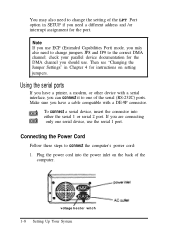
... other device with a serial interface, you have a cable compatible with a DE-9P connector. Make sure you can connect it to one serial device, use . To connect a serial device, insert the connector into the power inlet on the back of the LPT Port option in Chapter 4 for instructions on setting jumpers. If you need a different address and /or interrupt assignment for the DMA channel you máy also need to connect the computer's power cord...
... other device with a serial interface, you have a cable compatible with a DE-9P connector. Make sure you can connect it to one serial device, use . To connect a serial device, insert the connector into the power inlet on the back of the LPT Port option in Chapter 4 for instructions on setting jumpers. If you need a different address and /or interrupt assignment for the DMA channel you máy also need to connect the computer's power cord...

User Manual
Page 30
... BIOS ROM (basic input/ output system read-only memory) chip on the system board. You may also want to install drivers and utilities for your hardware configuration, security options, and power-saving features that SETUP allows you to install these drivers if you turn off or reset the computer. You only need to change. Running SETUP and lnstalling Drivers 2-1 This chapter describes the following procedures: Starting the SETUP program Using the System Setup options Using the Fixed Disk Setup option Using...
... BIOS ROM (basic input/ output system read-only memory) chip on the system board. You may also want to install drivers and utilities for your hardware configuration, security options, and power-saving features that SETUP allows you to install these drivers if you turn off or reset the computer. You only need to change. Running SETUP and lnstalling Drivers 2-1 This chapter describes the following procedures: Starting the SETUP program Using the System Setup options Using the Fixed Disk Setup option Using...
User Manual
Page 34
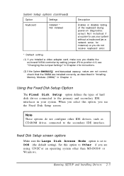
... Enables or disables testing of hard disk drives connected to DOS (the default setting). see the Fixed Disk Setup screen. When you select this option to Other if you are installed correctly, as described in "Installing Memory Modules (SIMMs)" in your system without a keyboard (as CD-ROM drives, connected to position 2-3; Note These options do not receive keyboard errors * Default setting (1) If you installed a video adapter card, make sure you disable the on-board SVGA controller by setting jumper JP2 to the secondary IDE interface. Running SETUP...
... Enables or disables testing of hard disk drives connected to DOS (the default setting). see the Fixed Disk Setup screen. When you select this option to Other if you are installed correctly, as described in "Installing Memory Modules (SIMMs)" in your system without a keyboard (as CD-ROM drives, connected to position 2-3; Note These options do not receive keyboard errors * Default setting (1) If you installed a video adapter card, make sure you disable the on-board SVGA controller by setting jumper JP2 to the secondary IDE interface. Running SETUP...

User Manual
Page 35
... hard disk uses in multiple sector transfers. On the screen that drive, press Enter to select the Autotype Fixed Disk option. The system detects the type of hard disk drive, fills in Chapters 5 and 6.) Individual drive options Your computer comes with a hard disk auto-sensing feature. Some older drives may also need to define your drive, you need to set the remaining options on the drive's jumper settings, described in the drive's parameters, and sets the remaining options...
... hard disk uses in multiple sector transfers. On the screen that drive, press Enter to select the Autotype Fixed Disk option. The system detects the type of hard disk drive, fills in Chapters 5 and 6.) Individual drive options Your computer comes with a hard disk auto-sensing feature. Some older drives may also need to define your drive, you need to set the remaining options on the drive's jumper settings, described in the drive's parameters, and sets the remaining options...
User Manual
Page 41
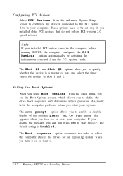
... before running SETUP, the computer configures the P C I Devices options automatically by detecting the information returned from the PCI option cards. The Slot #l and Slot #2 options allow you to start your computer. The default setting is a master or not, and select the timer values for an operating system when you installed PCI option cards in slots 1 and 2. If you disable the message, you turn it . 2-12 Running SETUP and Installing Drivers Note If you turn on or reset it...
... before running SETUP, the computer configures the P C I Devices options automatically by detecting the information returned from the PCI option cards. The Slot #l and Slot #2 options allow you to start your computer. The default setting is a master or not, and select the timer values for an operating system when you installed PCI option cards in slots 1 and 2. If you disable the message, you turn it . 2-12 Running SETUP and Installing Drivers Note If you turn on or reset it...
User Manual
Page 49
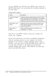
... interfaces for hard disk drives and other IDE devices. 2-20 Running SETUP and Installing Drivers To leave SETUP, press ESC from CMOS Save Values to CMOS Description Loads the factory default settings stored in ROM back into CMOS: if you change your configuration using SETUP and then have problems, you can perform the following functions in CMOS for all SETUP options: ignores any SETUP screen. From the SETUP Main Menu, you need for maximum performance with the operating system on...
... interfaces for hard disk drives and other IDE devices. 2-20 Running SETUP and Installing Drivers To leave SETUP, press ESC from CMOS Save Values to CMOS Description Loads the factory default settings stored in ROM back into CMOS: if you change your configuration using SETUP and then have problems, you can perform the following functions in CMOS for all SETUP options: ignores any SETUP screen. From the SETUP Main Menu, you need for maximum performance with the operating system on...

User Manual
Page 73
... Off On Installing and Removing Options 4-9 Do not change jumper settings, if necessary. Note Any jumpers not listed in this section to locate jumpers.) Use the information in the following tables are for service purposes only. CPU clock jumper settings CPU clock speed * 50 MHz (for 75 MHz CPU) 60 MHz (for 90 MHz CPU) 66 MHz (for 100 MHz CPU) JP16 pins 1-2 Off Off On JP16 pins 3-4 Off On On * Default setting depends...
... Off On Installing and Removing Options 4-9 Do not change jumper settings, if necessary. Note Any jumpers not listed in this section to locate jumpers.) Use the information in the following tables are for service purposes only. CPU clock jumper settings CPU clock speed * 50 MHz (for 75 MHz CPU) 60 MHz (for 90 MHz CPU) 66 MHz (for 100 MHz CPU) JP16 pins 1-2 Off Off On JP16 pins 3-4 Off On On * Default setting depends...

User Manual
Page 74
... SlMMs Enable IDE controller Disable IDE controller Double- see "Removing an Option Card" for instructions. 4-10 Installing and Removing Options Refer to the illustration under "Locating the System Board Components" to access the jumpers; and single-sided SlMMs Single-sided SlMMs only * Default setting Setting the Jumpers To change a jumper setting, follow these steps: 1. Miscellcmeous jumper settings Jumper number JP2 JP6 JP12 Jumper setting 1-2 * 2-3 On Off * 1-2 * 2-3 JP13 JP14 Off * On 1-2, 3-4 2-3 * Function Enable VGA controller Disable VGA controller Clears the CMOS SETUP...
... SlMMs Enable IDE controller Disable IDE controller Double- see "Removing an Option Card" for instructions. 4-10 Installing and Removing Options Refer to the illustration under "Locating the System Board Components" to access the jumpers; and single-sided SlMMs Single-sided SlMMs only * Default setting Setting the Jumpers To change a jumper setting, follow these steps: 1. Miscellcmeous jumper settings Jumper number JP2 JP6 JP12 Jumper setting 1-2 * 2-3 On Off * 1-2 * 2-3 JP13 JP14 Off * On 1-2, 3-4 2-3 * Function Enable VGA controller Disable VGA controller Clears the CMOS SETUP...
User Manual
Page 88
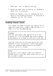
..., 15ns SRAM DIP chips. see "Installing an Option Card" for instructions on configuring your Authorized EPSON Servicer or the EPSON Connection and ask for you removed; Then see "Post-installation Procedures" for instructions. 7. Installing External Cache Your computer has 256KB of cache chip. do not install any option cards you ; Replace any other chip. 6. see "Replacing the Cover." Caution The only cache memory chips approved for use in the illustrations. You can...
..., 15ns SRAM DIP chips. see "Installing an Option Card" for instructions on configuring your Authorized EPSON Servicer or the EPSON Connection and ask for you removed; Then see "Post-installation Procedures" for instructions. 7. Installing External Cache Your computer has 256KB of cache chip. do not install any option cards you ; Replace any other chip. 6. see "Replacing the Cover." Caution The only cache memory chips approved for use in the illustrations. You can...
User Manual
Page 107
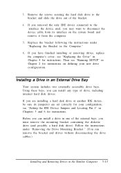
... the drive out of drive, including internal hard disk drives. If you have finished installing or removing drives, replace the computer's cover; If you are set correctly for instructions. Follow the instructions under "Replacing the Bracket in the Computer." 6. Then see "Setting the IDE Device Jumpers and Locating Pin 1" in an External Drive Bay Your system includes two externally accessible drive bays. Installing a Drive in Chapters 5 and 6 for instructions on the system board and remove it from the computer. 5. see "Running SETUP...
... the drive out of drive, including internal hard disk drives. If you have finished installing or removing drives, replace the computer's cover; If you are set correctly for instructions. Follow the instructions under "Replacing the Bracket in the Computer." 6. Then see "Setting the IDE Device Jumpers and Locating Pin 1" in an External Drive Bay Your system includes two externally accessible drive bays. Installing a Drive in Chapters 5 and 6 for instructions on the system board and remove it from the computer. 5. see "Running SETUP...
User Manual
Page 144
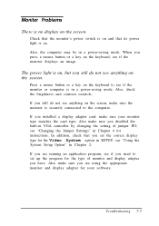
... a power-saving mode. In addition, check that its power light is on the screen. When you press a mouse button or a key on , but you have. Also make sure the monitor is on the keyboard, see if you are using the appropriate monitor and display adapter for the Video System option in a power-saving mode. If you need to the computer. Troubleshooting 7-7 The power light is securely connected to set the correct display type for your monitor type matches the card type...
... a power-saving mode. In addition, check that its power light is on the screen. When you press a mouse button or a key on , but you have. Also make sure the monitor is on the keyboard, see if you are using the appropriate monitor and display adapter for the Video System option in a power-saving mode. If you need to the computer. Troubleshooting 7-7 The power light is securely connected to set the correct display type for your monitor type matches the card type...
User Manual
Page 153
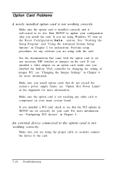
... external device connected to the card. 7-16 Troubleshooting If you install the card. See "Starting the Setup Program" and "Using the Advanced System Setup 0ptions" in its slot. see "Changing the Jumper Settings" in Chapter 2. Run SETUP to update your configuration after you installed a PCI card, check to set correctly for more information. Perform setup procedures for instructions. See the documentation that do not exceed the system's power supply limits; Make sure you are using Windows 95, turn on the Reset Configuration Data option. Make...
... external device connected to the card. 7-16 Troubleshooting If you install the card. See "Starting the Setup Program" and "Using the Advanced System Setup 0ptions" in its slot. see "Changing the Jumper Settings" in Chapter 2. Run SETUP to update your configuration after you installed a PCI card, check to set correctly for more information. Perform setup procedures for instructions. See the documentation that do not exceed the system's power supply limits; Make sure you are using Windows 95, turn on the Reset Configuration Data option. Make...
User Manual
Page 180
... of computer, A-7 Diagnostics, power-on, 1-11, 2-13, 7-3, 7-17 DIP chips, see Video memory Disk optimization utility, 7-12 Diskette drive accessing, 2-15, 3-11, 7-9, A-6 bays, 1-10,4-6-7,5-2,5-13, 5-15-18, 5-20-21 boot sequence, 2-13, 7-3 cable, 5-4, 5-11-12, 5-14, 5-17, 5-20, 6-11 combo, A-4 configuring, 7-10 connectors, 4-8, 5-4, 5-11, 5-18 controller, A-4 errors, 7-9-10 installing, slimline computer, 5-1-22 installing, tower computer, 6-1-22 interface, 4-8 light, 3-9 power supply cable, 6-12 problems, 7-10 removing, 5-4-5, 5-20-21 restricting access, 2-15, 3-11, 7-9, A-6 types, A-6 2 Index
... of computer, A-7 Diagnostics, power-on, 1-11, 2-13, 7-3, 7-17 DIP chips, see Video memory Disk optimization utility, 7-12 Diskette drive accessing, 2-15, 3-11, 7-9, A-6 bays, 1-10,4-6-7,5-2,5-13, 5-15-18, 5-20-21 boot sequence, 2-13, 7-3 cable, 5-4, 5-11-12, 5-14, 5-17, 5-20, 6-11 combo, A-4 configuring, 7-10 connectors, 4-8, 5-4, 5-11, 5-18 controller, A-4 errors, 7-9-10 installing, slimline computer, 5-1-22 installing, tower computer, 6-1-22 interface, 4-8 light, 3-9 power supply cable, 6-12 problems, 7-10 removing, 5-4-5, 5-20-21 restricting access, 2-15, 3-11, 7-9, A-6 types, A-6 2 Index

User Manual
Page 181
..., A-8 Environments, tested operating, A-15 EPSON, contacting, Intro-6 Ergonomic tips, 3-1-5 Errors controller, 7-18 diskette drive, 7-9-10 hard disk drive, 7-1 1-12 keyboard, 7-6 mouse, 7-6 power-on diagnostics, 1-11 read/ write, 7-12 Expansion buses ISA, Intro-3 PCI, Intro-3 External cache, Intro-2, see also Cache memory F Faceplate removing, 5-15, 6-10 replacing, 5-21 Files AUTOEXEC.BAT, 7-3 CONFIG.SYS, 2-22, 7-3 readme, 2-23 repairing, 7-10 SYSTEM.INI, 2-22 Fixed Disk Setup option, 2-5, 2-7 32 Bit I/ O, 2-7 Autotype Fixed Disk, 2-6 Large Disk Access Mode, 2-5 LBA Mode Control, 2-7 Multi...
..., A-8 Environments, tested operating, A-15 EPSON, contacting, Intro-6 Ergonomic tips, 3-1-5 Errors controller, 7-18 diskette drive, 7-9-10 hard disk drive, 7-1 1-12 keyboard, 7-6 mouse, 7-6 power-on diagnostics, 1-11 read/ write, 7-12 Expansion buses ISA, Intro-3 PCI, Intro-3 External cache, Intro-2, see also Cache memory F Faceplate removing, 5-15, 6-10 replacing, 5-21 Files AUTOEXEC.BAT, 7-3 CONFIG.SYS, 2-22, 7-3 readme, 2-23 repairing, 7-10 SYSTEM.INI, 2-22 Fixed Disk Setup option, 2-5, 2-7 32 Bit I/ O, 2-7 Autotype Fixed Disk, 2-6 Large Disk Access Mode, 2-5 LBA Mode Control, 2-7 Multi...

User Manual
Page 183
... B port, 1-4, see also Keyboard Keyboard connecting, 1-3-5 errors, 7-6 port, 1-3-4, 4-8, A-5 problems, 7-6 specifications, A-6 using, 3-4 Keypad, numeric, 7-6 Keys, SETUP function, 2-3 L Lighting workspace, 3-3-4 Lights, see Indicator lights Location, choosing, 1-1-2 Lockup problems, 7-5 LPT Extended Mode, 1-7 M Main menu, SETUP, 2-2 Mass storage, Intro-2, 5-2, 6-2, A-5-6 Master hard disk drive, 2-7, 5-2, 5-13, 6-3, A-11 Math coprocessor, A-3 Measurements, computer, A-7 Memory addresses, Intro-3 banks, 4-8, 4-12 BIOS ROM, 2-1 cache, see Cache memory clearing, 3-10 CMOS RAM, A-3 configurations...
... B port, 1-4, see also Keyboard Keyboard connecting, 1-3-5 errors, 7-6 port, 1-3-4, 4-8, A-5 problems, 7-6 specifications, A-6 using, 3-4 Keypad, numeric, 7-6 Keys, SETUP function, 2-3 L Lighting workspace, 3-3-4 Lights, see Indicator lights Location, choosing, 1-1-2 Lockup problems, 7-5 LPT Extended Mode, 1-7 M Main menu, SETUP, 2-2 Mass storage, Intro-2, 5-2, 6-2, A-5-6 Master hard disk drive, 2-7, 5-2, 5-13, 6-3, A-11 Math coprocessor, A-3 Measurements, computer, A-7 Memory addresses, Intro-3 banks, 4-8, 4-12 BIOS ROM, 2-1 cache, see Cache memory clearing, 3-10 CMOS RAM, A-3 configurations...

User Manual
Page 185
... voltage selector switch, 1-2 Power-on diagnostics, 1-11, 2-13, 7-3, 7-17 Power-saving modes, 3-6-7 Precautions, iii-vi, 1-1-2 Printer available options, A-15 connecting, 1-7 connector, 1-7 connector pin assignments, A-14 drivers, 7-15 port, 1-3, A-4 problems, 7-15 turning off, 1-11 turning on, 1-9 Processor, Intro-1, A-2 locating, 4-6-7 upgrading, 4-27-30 Processor speed, changing, 4-9 Program, stopping, 3-9 PS/ 2 compatible, 1-4, A-5-6 R RAM, Intro-1, 2-11, A-2 Random Access Memory, see RAM Read/ write errors, 7-12 Real-time clock, A-3 RESET button, 1-10, 3-10, 3-12 Resetting the computer...
... voltage selector switch, 1-2 Power-on diagnostics, 1-11, 2-13, 7-3, 7-17 Power-saving modes, 3-6-7 Precautions, iii-vi, 1-1-2 Printer available options, A-15 connecting, 1-7 connector, 1-7 connector pin assignments, A-14 drivers, 7-15 port, 1-3, A-4 problems, 7-15 turning off, 1-11 turning on, 1-9 Processor, Intro-1, A-2 locating, 4-6-7 upgrading, 4-27-30 Processor speed, changing, 4-9 Program, stopping, 3-9 PS/ 2 compatible, 1-4, A-5-6 R RAM, Intro-1, 2-11, A-2 Random Access Memory, see RAM Read/ write errors, 7-12 Real-time clock, A-3 RESET button, 1-10, 3-10, 3-12 Resetting the computer...

User Manual
Page 187
...True Color support, A-9 Turning off computer, 1-11 Turning on computer, 1-9-10 U Upgrading processor, 4-27-30 User password, see Password User-defined hard disk drive, 2-7 V VGA controller, Intro-2, 4-10, 4-17 monitor, 1-5-6 port, 1-3-5,4-8, see Video Video BIOS, Intro-3 colors, A-3, A-9 connector, 1-3-5, A-4 controller, A-3 DIP chips, see Video memory drivers, 2-1, 2-22 port, 1-3-5, A-4 problems, 7-7-8 resolutions, A-3, A-9 SOJDRAM chips, 4-22, A-2 standby mode, 2-17, 3-6, 7-7, A-2 time-out, 2-17, 3-7 Video memory installing, 4-22-23 location, 4-6, 4-8 requirements, A-9 specifications, Intro...
...True Color support, A-9 Turning off computer, 1-11 Turning on computer, 1-9-10 U Upgrading processor, 4-27-30 User password, see Password User-defined hard disk drive, 2-7 V VGA controller, Intro-2, 4-10, 4-17 monitor, 1-5-6 port, 1-3-5,4-8, see Video Video BIOS, Intro-3 colors, A-3, A-9 connector, 1-3-5, A-4 controller, A-3 DIP chips, see Video memory drivers, 2-1, 2-22 port, 1-3-5, A-4 problems, 7-7-8 resolutions, A-3, A-9 SOJDRAM chips, 4-22, A-2 standby mode, 2-17, 3-6, 7-7, A-2 time-out, 2-17, 3-7 Video memory installing, 4-22-23 location, 4-6, 4-8 requirements, A-9 specifications, Intro...


