
Service Manual
Page 9
EPSON Stylus Pro 7600/9600 Revision A 4.3 Disassembly and Assembly of Carriage (CR) Mechanism 171 4.3.1 Print Head 171 4.3.2 Damper ASSY 173 4.3.3 CR Board ASSY 174 4.3.4 Cutter Section 175 4.3.4.1 Cutter Holder ASSY 175 4.3.4.2 Cutter Solenoid 177 4.3.5 ... Cover Sensor ASSY Adjustment 216 5.1.4.10 PF Encoder Sensor ASSY Adjustment 216 5.1.4.11 Cutter Solenoid ASSY or Paper Guide L Adjustment 217 5.1.4.12 Damper ASSY Adjustment 217 5.1.4.13 Release Sensor (I/H Lever) Adjustment 217 5.1.4.14 Battery 217 5.1.5 Parameter Backup 218 5.1.5.1 Parameter Backup Procedure 218 5.1.5.2 ...
EPSON Stylus Pro 7600/9600 Revision A 4.3 Disassembly and Assembly of Carriage (CR) Mechanism 171 4.3.1 Print Head 171 4.3.2 Damper ASSY 173 4.3.3 CR Board ASSY 174 4.3.4 Cutter Section 175 4.3.4.1 Cutter Holder ASSY 175 4.3.4.2 Cutter Solenoid 177 4.3.5 ... Cover Sensor ASSY Adjustment 216 5.1.4.10 PF Encoder Sensor ASSY Adjustment 216 5.1.4.11 Cutter Solenoid ASSY or Paper Guide L Adjustment 217 5.1.4.12 Damper ASSY Adjustment 217 5.1.4.13 Release Sensor (I/H Lever) Adjustment 217 5.1.4.14 Battery 217 5.1.5 Parameter Backup 218 5.1.5.1 Parameter Backup Procedure 218 5.1.5.2 ...

Service Manual
Page 117
... the CSIC Relay Board in each color head damper Pump motor (stepping motor) (p.115) To print head Figure 2-16. EPSON Stylus Pro 7600/9600 2.2.4 Ink Supply Mechanism Stylus Pro 7600/9600 is so constructed that the 7 cartridges for different colors are placed on each color ink cartridge case to "Ink information... the right direction. † Explanation of valve mechanism mounted on the CSIC Board. The CSIC Board stores various pieces of the printer. Valve Mechanism The ink flow is mounted and removed. A projection and unique marking are installed in the respective ink holders (I...
... the CSIC Relay Board in each color head damper Pump motor (stepping motor) (p.115) To print head Figure 2-16. EPSON Stylus Pro 7600/9600 2.2.4 Ink Supply Mechanism Stylus Pro 7600/9600 is so constructed that the 7 cartridges for different colors are placed on each color ink cartridge case to "Ink information... the right direction. † Explanation of valve mechanism mounted on the CSIC Board. The CSIC Board stores various pieces of the printer. Valve Mechanism The ink flow is mounted and removed. A projection and unique marking are installed in the respective ink holders (I...

Service Manual
Page 147
...the insides of the heads, so sufficient caution should be checked. EPSON Stylus Pro 7600/9600 Revision A 3.3 Troubleshooting Based on Your Printout This section describes ..., etc.) „ If the trouble occurs with a specific ink color: • Abnormal connections between the ink cartridge, ink holder, tube, damper, print head. (Fastening nuts loose, or the O-ring deformed or...another Maintenance Tank as a spare.) † The actions above do not work to recover the printer, check the following particulars. † Execute powerful cleaning of Selfdiagnostic Function (p.220). (Power OFF&#...
...the insides of the heads, so sufficient caution should be checked. EPSON Stylus Pro 7600/9600 Revision A 3.3 Troubleshooting Based on Your Printout This section describes ..., etc.) „ If the trouble occurs with a specific ink color: • Abnormal connections between the ink cartridge, ink holder, tube, damper, print head. (Fastening nuts loose, or the O-ring deformed or...another Maintenance Tank as a spare.) † The actions above do not work to recover the printer, check the following particulars. † Execute powerful cleaning of Selfdiagnostic Function (p.220). (Power OFF&#...

Service Manual
Page 157
... (p.192) 4.6 Disassembly and Assembly of Cleaning Mechanism (p.198) 4.7 Disassembly and Assembly of Circuit Boards (p.205) Disassembly & Assembly Summary 157 EPSON Stylus Pro 7600/9600 Revision A 4.2.3 L Side Cover (p.163) 4.2.4 I/H Cover (p.164) 4.2.1 Panel Unit (p.159) 4.2.2 R Side Cover (p.160) 4.2.8 ...193) CSIC Relay Board (p.193) Note: The italic bold characters represent consumables or regular replacement parts. 4.3.1 Print Head (p.171) 4.3.2 Damper ASSY (p.173) 4.3.3 CR Board ASSY (p.174) 4.3.4 Cutter Section (p.175) 4.3.4.1 Cutter Holder ASSY (p.175) 4.3.4.2 Cutter Solenoid (p....
... (p.192) 4.6 Disassembly and Assembly of Cleaning Mechanism (p.198) 4.7 Disassembly and Assembly of Circuit Boards (p.205) Disassembly & Assembly Summary 157 EPSON Stylus Pro 7600/9600 Revision A 4.2.3 L Side Cover (p.163) 4.2.4 I/H Cover (p.164) 4.2.1 Panel Unit (p.159) 4.2.2 R Side Cover (p.160) 4.2.8 ...193) CSIC Relay Board (p.193) Note: The italic bold characters represent consumables or regular replacement parts. 4.3.1 Print Head (p.171) 4.3.2 Damper ASSY (p.173) 4.3.3 CR Board ASSY (p.174) 4.3.4 Cutter Section (p.175) 4.3.4.1 Cutter Holder ASSY (p.175) 4.3.4.2 Cutter Solenoid (p....

Service Manual
Page 171
EPSON Stylus Pro 7600/9600 4.3 Disassembly and Assembly of the Damper with your fingers so that no significant load is applied to the ink tubes. „ There is a hook 2 cm high at the center of Carriage (CR) Mechanism 171 CHECK P O IN T When replacing the print head with the print head. Install the Damper...bottom plate of the CR Board Assy so that work , you are advised to the printer center. (See Figure 4-24) 3. In addition, for easier work will not be damaged. Damper Holder Loosening Disassembly & Assembly Disassembly and Assembly of the head. While pushing the cutter ...
EPSON Stylus Pro 7600/9600 4.3 Disassembly and Assembly of the Damper with your fingers so that no significant load is applied to the ink tubes. „ There is a hook 2 cm high at the center of Carriage (CR) Mechanism 171 CHECK P O IN T When replacing the print head with the print head. Install the Damper...bottom plate of the CR Board Assy so that work , you are advised to the printer center. (See Figure 4-24) 3. In addition, for easier work will not be damaged. Damper Holder Loosening Disassembly & Assembly Disassembly and Assembly of the head. While pushing the cutter ...

Service Manual
Page 173
... of Carriage (CR) Mechanism 173 Install the Damper Unit with care not to the printer center. (See Figure 4-24) 3. Damper Holder Removal Coupling screw Damper ASSY Figure 4-29. Damper ASSY Removal Damper Holder Disassembly & Assembly Disassembly and Assembly of the Damper Holder and remove the Damper Holder. (See Figure 4-28) 5. EPSON Stylus Pro 7600/9600 4.3.2 Damper ASSY CHECK P O IN T Execute ink discharge ("Ink...
... of Carriage (CR) Mechanism 173 Install the Damper Unit with care not to the printer center. (See Figure 4-24) 3. Damper Holder Removal Coupling screw Damper ASSY Figure 4-29. Damper ASSY Removal Damper Holder Disassembly & Assembly Disassembly and Assembly of the Damper Holder and remove the Damper Holder. (See Figure 4-28) 5. EPSON Stylus Pro 7600/9600 4.3.2 Damper ASSY CHECK P O IN T Execute ink discharge ("Ink...

Service Manual
Page 212
... operations, the specified adjustment items should be made once the Print Head (p.171) has been replaced. EPSON Stylus Pro 7600/9600 Revision A 5.1.3 Procedure for Adjustment Work Follow the specified steps by consulting "5.2 Self-diagnostic Function" (p.220) and "5.3 Mechanism Adjustment"...Sensor_0.3 ASSY (p.190) CR Encoder Sensor ASSY (p.178) Cover Sensor ASSY (p.197) PF Encoder Sensor ASSY (p.186) Cutter Solenoid (p.177) Paper Guide L2 (p.168) Damper ASSY (p.173) Release Sensor (I/H Lever) (p.193) See for Adjustment p. 212 p. 213 p. 214 p. 214 p. 215 p. 215 p. 215 p. 215 p. 216...
... operations, the specified adjustment items should be made once the Print Head (p.171) has been replaced. EPSON Stylus Pro 7600/9600 Revision A 5.1.3 Procedure for Adjustment Work Follow the specified steps by consulting "5.2 Self-diagnostic Function" (p.220) and "5.3 Mechanism Adjustment"...Sensor_0.3 ASSY (p.190) CR Encoder Sensor ASSY (p.178) Cover Sensor ASSY (p.197) PF Encoder Sensor ASSY (p.186) Cutter Solenoid (p.177) Paper Guide L2 (p.168) Damper ASSY (p.173) Release Sensor (I/H Lever) (p.193) See for Adjustment p. 212 p. 213 p. 214 p. 214 p. 215 p. 215 p. 215 p. 215 p. 216...

Service Manual
Page 217
EPSON Stylus Pro 7600/9600 Revision A 5.1.4.11 Cutter Solenoid ASSY or Paper Guide L Adjustment Described below are the adjustment items to "5.2.3.20 Clean Head (p.256)". „ Secure the coupling screw .... † Adjusting tools: „ Cutter Positioning Jig #F800 „ Scale 1000mm #F713 „ Scale Stopper #F714 † Adjustment items (steps): Table 5-13. Required Adjustment Items (Damper ASSY) Step Adjustment Item (Power OFF → [Paper Feed ∆]+[Paper Feed ∇]+[Cut/Eject] → Power ON) 1 Including initial filling 2 Head Nozzle Checking (Cleaning...
EPSON Stylus Pro 7600/9600 Revision A 5.1.4.11 Cutter Solenoid ASSY or Paper Guide L Adjustment Described below are the adjustment items to "5.2.3.20 Clean Head (p.256)". „ Secure the coupling screw .... † Adjusting tools: „ Cutter Positioning Jig #F800 „ Scale 1000mm #F713 „ Scale Stopper #F714 † Adjustment items (steps): Table 5-13. Required Adjustment Items (Damper ASSY) Step Adjustment Item (Power OFF → [Paper Feed ∆]+[Paper Feed ∇]+[Cut/Eject] → Power ON) 1 Including initial filling 2 Head Nozzle Checking (Cleaning...
Service Manual
Page 233
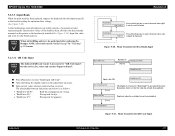
...error has occurred. Press [SelecType] key to the head already mounted on the printer or the head newly installed (See Figure 5-24). Figure 5-20. Displayed when the cartridge has not been installed. EPSON Stylus Pro 7600/9600 5.2.3.3 Input Rank When the print head has been replaced, input as follows:...Rank Input : ? Remember, however, that the rank has already been updated. Press [SelecType] key to be performed after replacing the Damper ASSY, select and execute "Initial charge" in the Flash memory. The relationship between indications and errors is input on the panel. ...
...error has occurred. Press [SelecType] key to the head already mounted on the printer or the head newly installed (See Figure 5-24). Figure 5-20. Displayed when the cartridge has not been installed. EPSON Stylus Pro 7600/9600 5.2.3.3 Input Rank When the print head has been replaced, input as follows:...Rank Input : ? Remember, however, that the rank has already been updated. Press [SelecType] key to be performed after replacing the Damper ASSY, select and execute "Initial charge" in the Flash memory. The relationship between indications and errors is input on the panel. ...

Service Manual
Page 259
... : ? [Paper Feed ∇] Print : ? [Paper Feed ∇] Print : ? [Paper Feed ∇] [SelecType] Check Ptn. ? Fill Initial filling CHECK P O IN T After replacing the Damper ASSY and/or ink tube, if ink charging is no dot missing. Std. Figure 5-60. Cleaning : ? Printing Items Display Contents Print: Check Ptn. KK1 Cleaning... 5-61 shows printing menu transition. Printing end [Paper Feed ∆] [SelecType] Check Ptn. 2 ? Printing Menu Transition Adjustment Self-diagnostic Function 259 Cleaning : ? EPSON Stylus Pro 7600/9600 5.2.4 Cleaning Execute head cleaning.
... : ? [Paper Feed ∇] Print : ? [Paper Feed ∇] Print : ? [Paper Feed ∇] [SelecType] Check Ptn. ? Fill Initial filling CHECK P O IN T After replacing the Damper ASSY and/or ink tube, if ink charging is no dot missing. Std. Figure 5-60. Cleaning : ? Printing Items Display Contents Print: Check Ptn. KK1 Cleaning... 5-61 shows printing menu transition. Printing end [Paper Feed ∆] [SelecType] Check Ptn. 2 ? Printing Menu Transition Adjustment Self-diagnostic Function 259 Cleaning : ? EPSON Stylus Pro 7600/9600 5.2.4 Cleaning Execute head cleaning.

Service Manual
Page 317
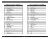
...LABEL LABEL LOGO PLATE 13X54 Appendix Revision A Table 7-6. PLASTIC STOPPER E5 FULONT COVER FUICRUM PIN L FRONT COVER ASSY. ASP List for Stylus Pro 7600 Ref No. 100 101 102 103 104 105 106 107 108 109 110 111 112 113 114 115 116 117 118 119 120... CATCH TOP COVER DAMPER DISK(TOPCOVER) UNDULATE WASHER(TOPCOVER) PANEL UNIT ASSY.(OVERSEAS) BRANK PANEL LEVER BRIND CAP PRSSURE LEVER KNOB PANEL TAPE CABLE ROLL TRAY R ASSY. R SIDE COVER ASSY. FRONT COVER SUPPLEMENT ROLL TRAY L ASSY. EPSON Stylus Pro 7600/9600 7.5 ASP List (Parts List) 7.5.1 ASP List for Stylus Pro 7600 (continued) Ref...
...LABEL LABEL LOGO PLATE 13X54 Appendix Revision A Table 7-6. PLASTIC STOPPER E5 FULONT COVER FUICRUM PIN L FRONT COVER ASSY. ASP List for Stylus Pro 7600 Ref No. 100 101 102 103 104 105 106 107 108 109 110 111 112 113 114 115 116 117 118 119 120... CATCH TOP COVER DAMPER DISK(TOPCOVER) UNDULATE WASHER(TOPCOVER) PANEL UNIT ASSY.(OVERSEAS) BRANK PANEL LEVER BRIND CAP PRSSURE LEVER KNOB PANEL TAPE CABLE ROLL TRAY R ASSY. R SIDE COVER ASSY. FRONT COVER SUPPLEMENT ROLL TRAY L ASSY. EPSON Stylus Pro 7600/9600 7.5 ASP List (Parts List) 7.5.1 ASP List for Stylus Pro 7600 (continued) Ref...
Service Manual
Page 318
... 570 DAMPER ASSY. 600 CR MOTOR 601 CR MOTOR CABLE ASSY.1 602 T FENCE SPRING 603 PRSSURE SPRING 604 T FENCE 605 P THICK SENSOR CABLE ASSY 606 PHOTO SENSOR 607 P THICK2 SENNSOR CABLE ASSY. 608 CR BELT 609 MINI CLAMP 610 CR DRIVE PULLEY ASSY. EPSON Stylus Pro 7600/9600 Table 7-6. Revision A Table 7-6. ASP List for Stylus Pro 7600...
... 570 DAMPER ASSY. 600 CR MOTOR 601 CR MOTOR CABLE ASSY.1 602 T FENCE SPRING 603 PRSSURE SPRING 604 T FENCE 605 P THICK SENSOR CABLE ASSY 606 PHOTO SENSOR 607 P THICK2 SENNSOR CABLE ASSY. 608 CR BELT 609 MINI CLAMP 610 CR DRIVE PULLEY ASSY. EPSON Stylus Pro 7600/9600 Table 7-6. Revision A Table 7-6. ASP List for Stylus Pro 7600...

Service Manual
Page 320
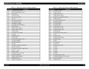
...SPRING 552 CUTTER SOLENOID ASSY. 553 CUTTER SPRING ASP List (Parts List) 320 FRONT COVER SUPPLEMENT ROLL TRAY L ASSY. EPSON Stylus Pro 7600/9600 7.5.2 ASP List for Stylus Pro 9600 Ref No. 100 101 102 103 104 105 106 107 108 109 110 111 112 113 114 115 116 117 118... ASSY. H TOP COVER ASSY. LABEL LABEL LABEL LABEL LABEL LABEL LOGO PLATE 13X54 LABEL LABEL LABEL FCC CLIP Appendix Revision A Table 7-7. CATCH TOP COVER DAMPER DISK(TOPCOVER) UNDULATE WASHER(TOPCOVER) PANEL UNIT ASSY.(OVERSEAS) BRANK PANEL LEVER BRIND CAP PRSSURE LEVER KNOB PANEL TAPE CABLE ROLL TRAY R ASSY. I /H ...
...SPRING 552 CUTTER SOLENOID ASSY. 553 CUTTER SPRING ASP List (Parts List) 320 FRONT COVER SUPPLEMENT ROLL TRAY L ASSY. EPSON Stylus Pro 7600/9600 7.5.2 ASP List for Stylus Pro 9600 Ref No. 100 101 102 103 104 105 106 107 108 109 110 111 112 113 114 115 116 117 118... ASSY. H TOP COVER ASSY. LABEL LABEL LABEL LABEL LABEL LABEL LOGO PLATE 13X54 LABEL LABEL LABEL FCC CLIP Appendix Revision A Table 7-7. CATCH TOP COVER DAMPER DISK(TOPCOVER) UNDULATE WASHER(TOPCOVER) PANEL UNIT ASSY.(OVERSEAS) BRANK PANEL LEVER BRIND CAP PRSSURE LEVER KNOB PANEL TAPE CABLE ROLL TRAY R ASSY. I /H ...
Service Manual
Page 321
...557 CR ENC ASSY. 558 CR LOCK KICKER 559 TILAP 560 H ADJUST LEVER B 561 H ADJUST LEVER 562 DAMPER STOPPER 563 DAMPER POSITION BOAD 564 PRINT HEAD 565 HEAD TAPE CABLE 1 566 HEAD TAPE CABLE 2 567 SLIDE GEAR 568 CONNECTING SCREW 569... O RING 570 DAMPER ASSY. 600 CR MOTOR 601 CR MOTER CABLE ASSY.2 602 T FENCE SPRING 603 PRSSURE SPRING 604 SCALE 605 ... CABLE 702 TR CONNECTER 703 POROUS PAD Appendix ASP List (Parts List) 321 EPSON Stylus Pro 7600/9600 Table 7-7.
...557 CR ENC ASSY. 558 CR LOCK KICKER 559 TILAP 560 H ADJUST LEVER B 561 H ADJUST LEVER 562 DAMPER STOPPER 563 DAMPER POSITION BOAD 564 PRINT HEAD 565 HEAD TAPE CABLE 1 566 HEAD TAPE CABLE 2 567 SLIDE GEAR 568 CONNECTING SCREW 569... O RING 570 DAMPER ASSY. 600 CR MOTOR 601 CR MOTER CABLE ASSY.2 602 T FENCE SPRING 603 PRSSURE SPRING 604 SCALE 605 ... CABLE 702 TR CONNECTER 703 POROUS PAD Appendix ASP List (Parts List) 321 EPSON Stylus Pro 7600/9600 Table 7-7.

